Reverse flushing the early BS38 carburetor pilot circuit (idle jet)

TwoManyXS1Bs

BBQ Hunter
Top Contributor
Messages
14,670
Reaction score
15,294
Points
813
Location
Fredericksburg, Texas
Laziness is the Mother of Invention

************************
This little project works on the 70-71 XS1/XS1B carburetors.
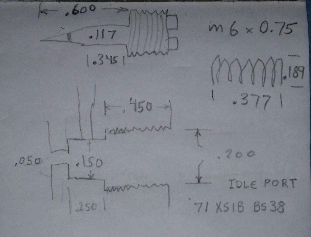
In 1972 (XS2), the carburetor bodies were revised, but the idle fuel (mixture) screws remained the same for years 1970-1975. As such, dimensions and procedures posted here may be applicable for carburetors up to 1975. For carburetors of 1976 and later, different dimensions will need to be found.

A visit to the forum's Tech section: Carburetors may be necessary to help understand the XS650 carburetors.
Also, if you haven't done so already, download and review the "Carb Guide" for an understanding of the pilot circuit.

http://www.amckayltd.com/carbguide.pdf

************************

When the Pilot Jet (idle jet) and/or the bleed air jet becomes inadvertently clogged, an effective quick fix can be done by reverse flushing of the pilot (idle) fuel circuit.

First, remove the bowl drain plug, drain the fuel into a suitable catch container.
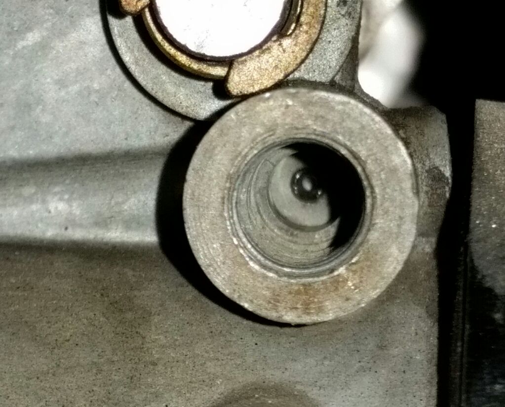
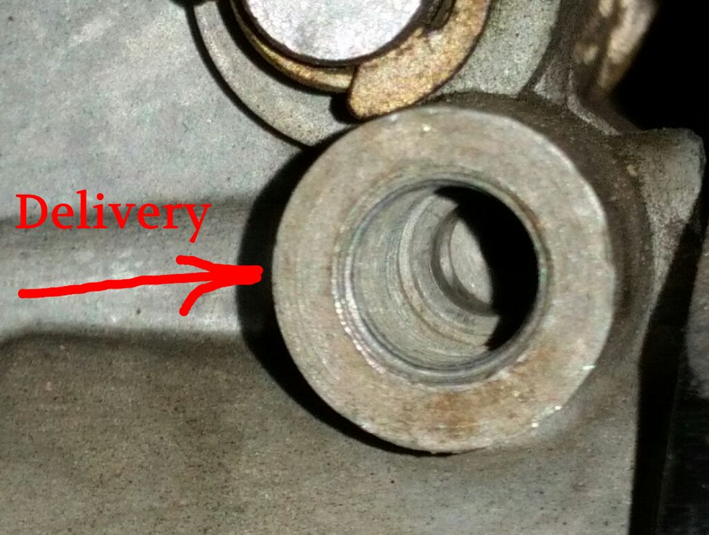
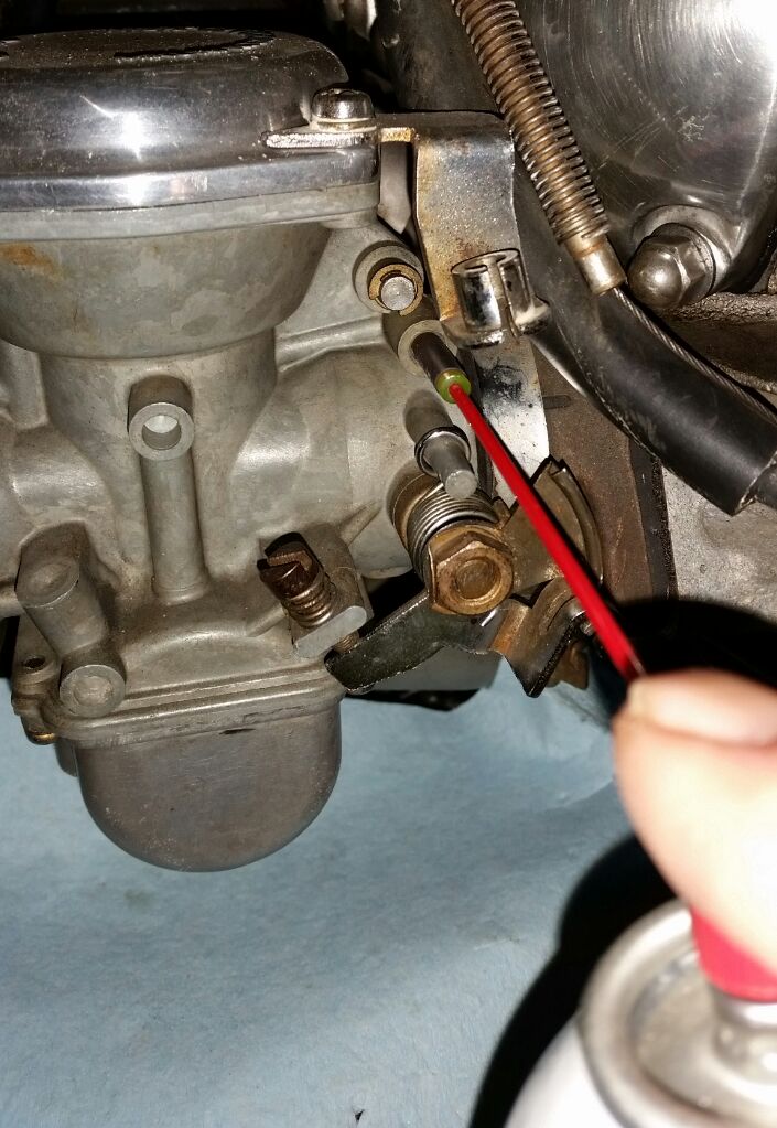
Then, remove the idle fuel (mix) screw. Insert the nozzle/tube of a can of carburetor cleaner into the port, and shoot a blast in there. The carb cleaner will spray into the pilot circuit, and hopefully dislodge any specks and contaminates back out of the pilot (idle) jet and idle air bleed jet.

The first problem with this method is that much of the carb cleaner will spray back, onto you, into your eyes, and not deliver much pressure into the fuel gallery.

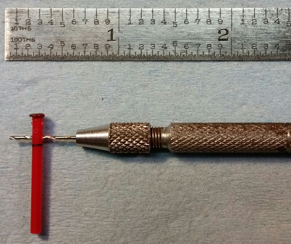
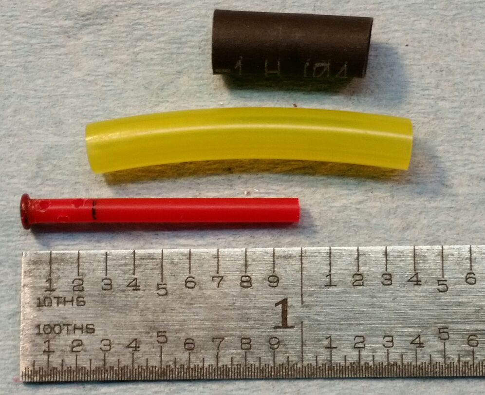
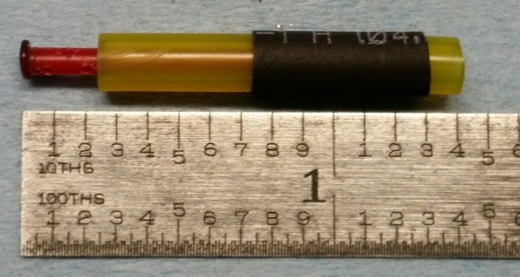
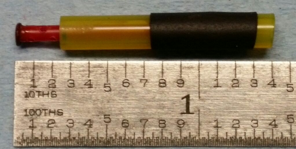
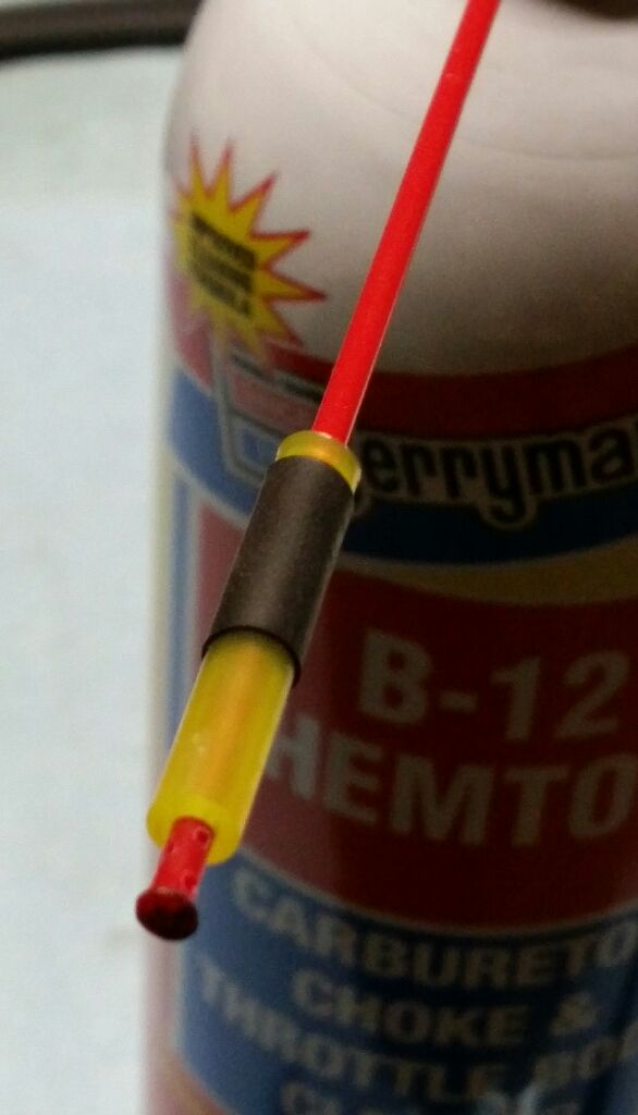
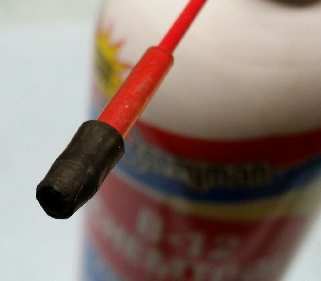
One solution is to fashion a fitment to the spray nozzle/tube that seals into the idle port opening.
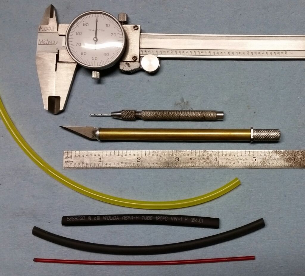
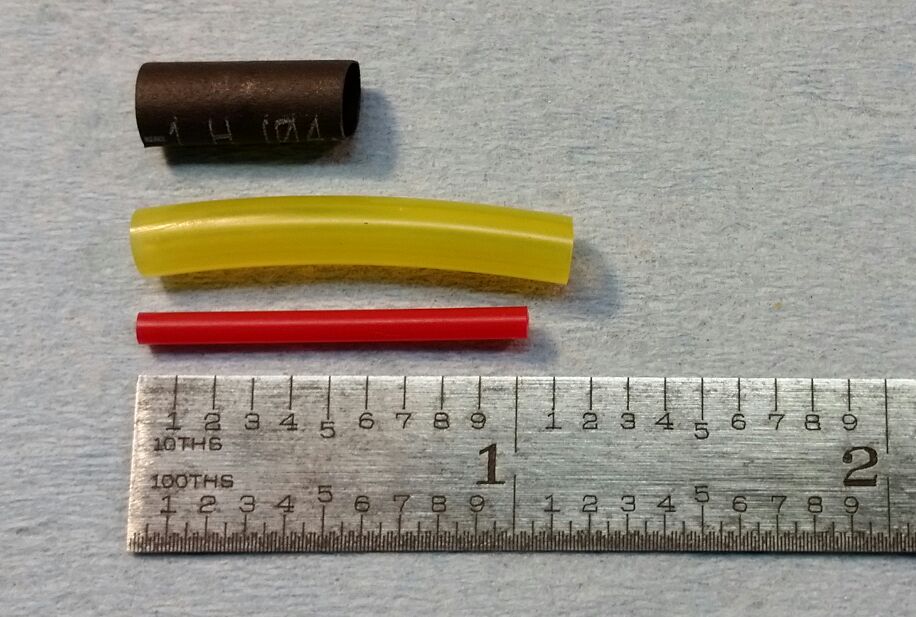
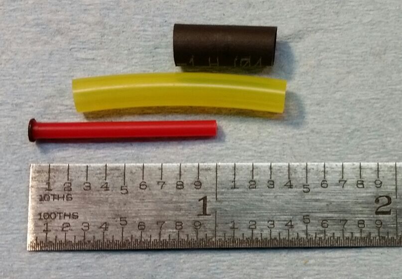
This one consists of a couple pieces of small tubing, formed like a tiny tapered cork.

full
 
The second problem with this method is that much of the carb cleaner will simply go directly into the idle port's discharge hole (where the screw's metering needle fits), especially if the nozzle/tube is inserted all the way into the back into the port opening. This is not where you want all that cleaner to go, and it will end up in the carburetor throat, requiring you to wait a long time for it to evaporate out. Here, you can see this metered discharge hole (about 0.050") at the back of the idle (mix) hole:

full


Ideally, we want a better method of getting the the carb cleaner to go only into the pilot fuel delivery gallery, with more pressure, which will enhance the reverse-flushing of the pilot (idle) jet and idle air bleed jet.

The pilot fuel delivery gallery emerges into the idle (mix) chamber from the side.
Just barely visible on the chamber side in this picture:

full


The transfer ports (little holes alongside the butterfly throttle valve, also known as transition ports, or by-pass holes in the carb guide) are also in this pilot circuit, and will be the first to receive this blast of cleaner. So, some cleaner will still enter the carburetor throat through these transfer ports.

FYI, the purpose of these transfer (transition, by-pass) ports is to ensure smooth transitioning of fuel delivery when the throttle is opened from idle to the low speed delivery of the needle jet and jet needle in the main circuit. They receive the majority of the fuel delivery from the pilot (idle) jet, and deliver most of the total fuel during low-speed cruise.
 
So, scratching up dimensions of the early BS38 idle (mix) screw and chamber, a workable carb spray nozzle adapter can be designed.

full


The goal for this nozzle adapter is threefold:

1- Seal off the outside, to maximise pressure and avoid sprayback
2- To seal off the idle discharge hole, to maximise pressure and reduce wasting cleaner
3- To divert the spray pattern to the sides, so that the cleaning fluid enters the pilot circuit
 
This normally would be an ideal project on a mini-lathe.
But, I wanted to cook up a craft project that would be easier for folks to tackle.
And, wanted to avoid having anything metallic that may damage the precious Zamak carburetor.

So, here's the tools and parts for this spray nozzle adapter:

full


The pin-vise is holding a small drillbit of about 0.032"

The greenish/yellowish tubing is soft/flexible Tygon fuel line, 3/16" OD, 3/32" ID
The actual dimensions are: 0.185" OD, 0.089" ID
When you buy it, ask for 3/32" Tygon fuel line. Used on chainsaws and such.

Below that, is black shrink tubing, your choice of sizes of 4mm or 3/16".
Either one works fine.

At the bottom is a red spray nozzle tube, found with many aerosol products.
I've found these nozzle tubes in a variety of diameters.
Some as small as 0.082", the majority at 0.084"-0.087", and one at 0.091"
The tube of choice here is something in the range of 0.086"-0.087" diameter.
A smaller one may not hold well, the largest one will interfere with the tygon tubing.

The idea here is that about 1/2" of the Tygon tubing needs to slide easily, but not too loosely, over the red tubing.
One end of it will be acting like a compression spring to make a seal on the idle chamber shoulder.
 
Cut a piece of the 3/16" (or 4mm) heatshrink to 1/2"
Cut a piece of the 3/32" Tygon tubing to 1-1/8"
Cut a piece of the 0.087" nozzle tube to just over 1"

Ensure that the cuts are clean/square/straight, especially on the Tygon tubing.
One end of this Tygon tubing will form the outer seal that prevents sprayback, so its end needs to be quite straight/square.

full
 
The next step is to melt and seal one end of the 0.087" red nozzle tube.

Just a short/quick dip of the tube's end into the edge of a small flame (like from a candle) is all that's needed. As soon as the end melts, gently press the melted end squarely onto a piece of smooth cold metal. You only want a thin closure of the end, but make sure that it is indeed closed off. And, keep the mushrooming diameter down to 1/8" or less. The finished total length needs to be 1".

This may take several tries to get it right. If so, do this on a full-length piece instead, cutting off the bad melt-job, until you get an end that's satisfactory. Then you can cut this piece to a 1" total length.

full


The other pieces are shown in their relative positions of the final assembly.
 
Next is cross-drilling of the spray holes.

Mark a line around the red nozzle tube, 1/4" from the sealed end.
Carefully cross-drill the tube with the 0.032" drill pin-vise, staying between the end and the 1/4" mark line.
Your drill pattern of choice, at least 2 holes for 4 spray holes.
Here, I've done 3 holes, for 6 spray holes.

full
 
The red plastic nozzle tube drills easily, but will leave some stringers and raised edges.

Spend some time here cleaning up the drilled holes. You can clean and chamfer the hole edges by spinning the knife point in the hole. Ensure that all holes are unblocked, clear and clean. Don't want any plastic slivers getting into fuel passages.

full
 
Assemble the pieces according to this picture.

You'll want the cleanest/squarest end of the Tygon tubing to be just a tad shy of 1/4" from the end of the red nozzle tube.
Maybe about 0.240" from the end.
With a chamber depth of 0.250", this will ensure that the soft Tygon tubing will seal inside the chamber shoulder when the adapter is pressed into place.

Fit the 3/16" (4mm) heat shrink tubing over the Tygon tubing, its edge at a 3/4", 0.750" distance from the end of the red nozzle tube.
The total depth into the chamber is 0.700", and Tygon tube with heatshrink on it won't fit into the 0.200" diameter opening, so you need a little extra clearance so it won't jam in there.

full
 
Finally, we heat-shrink the assembly, locking it into a single unit.

I use the heat from a small flame, like a candle flame, holding and slowly rotating the assembly about 1"-2" above the top edge of the flame, keeping the heat confined to the area of the heat-shrink tubing only. Careful here.

full


We now have a completed spray adapter.
 
Because of the extra 1/8" protuding Tygon tube at the fitment end, it will snugly fit onto any of the aforemention varieties of nozzle tube diameters. So, it can be used with any brand or type of aerosol carb cleaner.

The protuding Tygon tube at the entry end acts as a spring-loaded seal in the idle screw chamber.

In use, the adapter is gently pressed into the chamber, the mushroom end blocks off the idle discharge hole, and the cleaner spray is trapped in the chamber, forcing it into the adjacent pilot gallery.

full
 
Time to try it out.

Remove the bowl drain plug, drain the fuel into a suitable catch container.
Remove the idle fuel (mix) screw and its spring.
Place a napkin/towel under the bowl drain hole.
Insert the new nozzle adapter into the port, apply gentle pressure so it'll seal.
Shoost a blast in there.

Wow, a lot more solvent came out of the float bowl than ever before.

Give the solvent a couple minutes to do its work.
Repeat.

full
 
Here's the paper towel with the reverse-flushed mystery specks and contaminates.

full


The pilot jets used in my early carbs are #42.5, which have an orifice size slightly larger than 0.016".
I should've placed a 0.016" drill bit amongst the specks in this picture, to see the relative sizes.
But, most of these tiny specs are small enough to easily pass through the pilot jet orifice.
Or, maybe they already did...

******************************

I hope you enjoy this little project.

It took me about 1/2 hour to cut/drill/trim/assemble this adapter.

It took two days to assemble this thread...
 
wont capping the bypass holes with my thumb have the same effect? Instead of going into the throat, stuff gets blasted back into the bowl area?
 
I can see them rolling off some Chinese production line by the thousands. Cool idea!
 
I can see them rolling off some Chinese production line by the thousands. Cool idea!

Thanx, gggGary. I wuz doin' some research on production numbers, and I believe that our early bikes are rarer than 1909s VDB pennies. So, might not justify their going into production, dang it. Could've used one of these years ago...
 
Back
Top