Rotor Winding Tooling

I'm curious. 3 major parts of the rotor are,

The main core, with 4 fingers, the keyed taper bore, splines, and the threaded extraction nose.
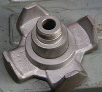
Rotor rewind03b.jpg

2nd, the front half rotor core, with 4 fingers, splined hole, threaded holes for the slipring plate.

3rd, the slipring plate, with the timing mark.

When these 3 are reassembled, is the alignment of the keyway with the timing mark assured, or do you have to keep your wits about you?
 
A week or so back, I took a cardboard box and about ten bucks worth of Chinese stuff and made a rotation counter.....

View attachment 122686
View attachment 122687
View attachment 122688

Today I made the rest of the wire coil winder/maker thingey.... I'm using the Atlas to make the coils, so I wanted something that was easy to install and remove. Glued and nailed two pieces of 3/4 ply together and added a simple angle to the back of it to grab the bed of the Atlas.

View attachment 122690

The drawer knob is to lock it in place. Installed another aluminum angle off the right side to install the counter on.

View attachment 122691
.
Added a spool holder to the bottom.

View attachment 122692
..... and a micro-switch for counting......

View attachment 122693

I was powering the counter from a USB charger but today I installed a 9v battery holder in the box. I went ahead and left the charger cord hooked up just in case... and used velcro to hold it.

View attachment 122694

It takes about 15 seconds to install or remove it.

View attachment 122695
Did a quick video of it in operation. The Atlas was at it's lowest speed. I'll play with the speed as I learn. I think before I wind any wire, I'm gonna make a foot switch addon for the Atlas so I have both hands free to tension and guide the wire. I'm guessin' the switch mechanism clinking is gonna get on my nerves.... so I'll order a hall effects switch for it....


G'day Jim,

Just lookng in the first photo...............looks like your hands have been up a dry gully or two.
 
.....looks like your hands have been up a dry gully or two.
Spent my life as a mechanic. Most of it outside on flightlines..... Been a few days since they had that "soft as a babies bum" feel to 'em... ;)
 
Last edited:
Excessive voltage drop across the diodes in the rectifier mean that the AC voltage from the stator must be higher to produce the required DC Voltage at the battery terminals to satisfy the regulator which is measuring the Voltage after the drop across the ignition switch contacts The higher AC voltage from the stator windings means that there has to be a proportionately higher current to the rotor which in turn causes the rotor to run hotter leading to early burn out. The voltage drop across the ignition switch also contributes to the need for higher current on the rotor because the voltage regulator is looking for a nominal 14.5 Volts on the brown wire from the ignition switch but if there is, say, a .5 Volt drop across the ignition switch, then the alternator through the rectifier has to produce 15 Volts to the battery, which also boils the battery. The higher current to the rotor also burns up the brushes as well. I "rectified" most of this destruction by installing a new rectifier and a relay that connects the input to the regulator directly to the battery so the regulator regulates the battery Voltage instead of the brown wire Voltage. Batteries last longer. The rotor goes forever and the brushes last longer.
 
Electronics potting material is designed for thermal expansion characteristics. Vibration would be the other thing to consider, but since it's a solid mass, might no be important.
From my research it's looking like the most important consideration for a rotor epoxy is "thermal conductivity." Most epoxy's have extremely poor thermal conductivity..... which leads to premature failure due to overheating. Those I've found so far.... the salesmen say.... "500 bucks minimum order." F&ck me...:(
Still lookin....
 
OK.... so here's where I'm at: I'll use either.....
MG Chemicals 4228-55ML Red Insulating Varnish
5119ZosQbiL._SY445_.jpg

It's called "alternator varnish." Best I can tell, it's what GM (or AC Delco) uses.....
or this......
710f3Jq-PAL._SY879_.jpg

.... to build the coils.
Then I'll wrap them with 3M glass cloth electrical tape #79 and this epoxy.....

MG Chemicals Thermally Conductive Epoxy Encapsulating and Potting Compound
81CSg5xLIWL._SX466_.jpg

.... and also use the epoxy to bond the coil inside the rotor. Should be practically indestructible.

I found the epoxy on Ebay for a very reasonable price. Fingers crossed.
 
Back
Top