-
Enjoy XS650.com? Consider making a donation to help support the site.
XS650.com receives a small share of sales from some links on this page, but direct donations have a much greater impact on keeping this site going.
You are using an out of date browser. It may not display this or other websites correctly.
You should upgrade or use an alternative browser.
You should upgrade or use an alternative browser.
Stator Fix/Adapt
- Thread starter BarrieC
- Start date


BarrieC
XS650 Addict
My final thought on this (Honest)
I can now see how Signals suggestion of "is the stator beyond redemption" applies now!
Would someone be kind enough to give me the measurements from the later screw on timing mark plate, T and F mark? this will do to get 'er running
Thanks
(slow learner from across the Pond)
I can now see how Signals suggestion of "is the stator beyond redemption" applies now!
Would someone be kind enough to give me the measurements from the later screw on timing mark plate, T and F mark? this will do to get 'er running
Thanks
(slow learner from across the Pond)
Last edited:
My popcorn was for seeing what Gary comes up with......") Never had occasion to attempt disassembly (Hondas yes, but they're made to come apart).
Never had occasion to attempt disassembly (Hondas yes, but they're made to come apart).
If the inside of the stator and pickup look ok, perhaps remove brush block and careful vapor blast outside only, followed by immediate washout with contact cleaner and WD40
Never had occasion to attempt disassembly (Hondas yes, but they're made to come apart).If the inside of the stator and pickup look ok, perhaps remove brush block and careful vapor blast outside only, followed by immediate washout with contact cleaner and WD40
BarrieC
XS650 Addict
Aah, I thought you might be sitting back enjoying watching my learning process again I don't really need to go as far as vapour blasting and i dont think it would improve the look of the casing (mostly me being precious about a "new" build. IF i use it, I will rotary wire brush it and then wet and dry using wd40
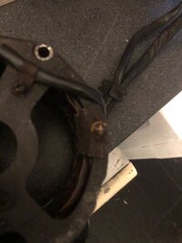
The insides look good, the Brushes are good even, but I do need to either replace that small screw on timing mark plate, or to avoid a sheared of screw, flat of the rust and remark it
I don't really need to go as far as vapour blasting and i dont think it would improve the look of the casing (mostly me being precious about a "new" build. IF i use it, I will rotary wire brush it and then wet and dry using wd40The insides look good, the Brushes are good even, but I do need to either replace that small screw on timing mark plate, or to avoid a sheared of screw, flat of the rust and remark it
Well if "Scrat" don't come up with anything, I'll give it a go. Got a shelf full to pick from.
Sorry for the delay had to go to a Christmas concert.


Got it out but not without some issues;
twisting of the laminations from uneven driving, the stator frame doesn't offer that great of access.
the brush wires are glued in a channel in the stator, didn't notice I was stretching them till the core was out.
I think an "expanding ring" tool that would bear on the inner ends of the coil spindles might allow one to drive it out straight.
probably didn't drill the fixing pins deep enough I think they might be just pins not screws?
used some mineral spirits as a lube between the stator and the laminations.
I didn't ohm the coils before I started, this stator had "been through it" in the past.
afterwards had about .7 ohms leg to leg no shorts to the frame.
Factory spec is .8 to 1.0 ohms. Low ohm measuring sucks on the VOM battery pretty hard. Takes several seconds of dropping numbers before display "settles" I think these are "in spec" yet.
Last edited:


See, we're all still learningAah, I thought you might be sitting back enjoying watching my learning process again
BarrieC
XS650 Addict
Thanks Gary, I really don't think I will be trying to do the swap now. Really appreciate your effortsbut I do need to either replace that small screw on timing mark plate, or to avoid a sheared of screw, flat of the rust and remark it
I probably should have sent this photo earlier, This is the timing marks plate, I just need the marks location from the edges of that plate, hope that makes sense
Thanks
Attachments
BarrieC
XS650 Addict
Fraid not, far too much rust! looks like my best bet is to measure on screen a picture of the plate and then scale it correctly and transfer those measurements.
Unless someone has a plate type, and could give me the measurements
Many thanks
Barrie
Unless someone has a plate type, and could give me the measurements
Many thanks
Barrie
I posted the info above.Fraid not, far too much rust! looks like my best bet is to measure on screen a picture of the plate and then scale it correctly and transfer those measurements.
Unless someone has a plate type, and could give me the measurements
Many thanks
Barrie
locate TDC with a piston stop. (it doesn't have to be very fancy, seriously a pencil would do it). then use the measurements.
Fwiw... I don't use that pointer to adjust/set a TCI system.... or any others for that matter. The drain at the bottom of the left cover starts at 40° and is down to 35° on the right. Set full advance to where you want it. The factory calls for 40°. I and others like 35-38°. The bike seems happier there.
Idle fire is what it is... the more important event is fire at max advance.

Idle fire is what it is... the more important event is fire at max advance.
BarrieC
XS650 Addict
got it guys! thanks for all your help 
I'm looking forward to doing the carbs and wiring the bike from scratch 2 things I can do (or could do before old age and Internet dependency crept in) LOL
I'm looking forward to doing the carbs and wiring the bike from scratch 2 things I can do (or could do before old age and Internet dependency crept in) LOL
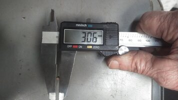
The coil assembly is attached to the frame with pins. Not getting one pin drilled all the way out is what bent this coil on the way out. The pins go about 5mm into the laminations, the frame is about 5 to 5.5mm thick where the pins are located. Steel pin of 3.06mm dia. in aluminum keeping a drill centered a bit touchy
Attachments
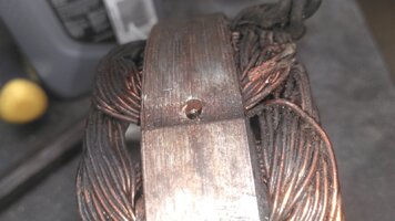
Pic showing the factory press in, a bit brutal. There was some evidence of varnish in the gap.
Notice the step where the frame ID is bigger, not machined, then the machined ID the frame presses into.
You want to free up/remove the pick up wires from their groove cuz they have nowhere to go as the coil assembly comes out, that groove does not extend all the way to base of the frame. Cut off the brush end connectors and break loose the "epoxy/filler that holds the wires in their groove. Remove the wires before drifting out the coil assembly.

key words; stator alternator windings armature rotor brushes repair replace frame varnish remove.
Notice the step where the frame ID is bigger, not machined, then the machined ID the frame presses into.
You want to free up/remove the pick up wires from their groove cuz they have nowhere to go as the coil assembly comes out, that groove does not extend all the way to base of the frame. Cut off the brush end connectors and break loose the "epoxy/filler that holds the wires in their groove. Remove the wires before drifting out the coil assembly.
key words; stator alternator windings armature rotor brushes repair replace frame varnish remove.
Last edited:
Drill press and a centering bit?Steel pin of 3.06mm dia. in aluminum keeping a drill centered a bit touchy
Fwiw... I don't use that pointer to adjust/set a TCI system.... or any others for that matter. The drain at the bottom of the left cover starts at 40° and is down to 35° on the right. Set full advance to where you want it. The factory calls for 40°. I and others like 35-38°. The bike seems happier there.
Idle fire is what it is... the more important event is fire at max advance.
View attachment 231408