Focus Research
XS650 New Member
Hi, I'm new here. I am helping a friend rework a pair of very tired, non-running XS650s, focusing on the electrics, since I am a degreed EE with plenty of test equipment.
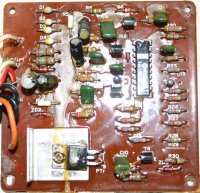
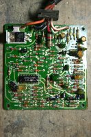
One of the bikes, a 1981, had the stock, non-function TCI box still attached to the bottom of the battery box, plus another unit tie-strapped on. Someone in the past bought the 2nd box from a junk yard and wired it in to make the bike run. The stock unit is labeled "TCI 12-01B" and the replacement "TCI 12-01", which is part of the story here. I opened both to compare them, and clearly the "01B" is a cost-reduced, later revision of the "01" unit. The "01" version has a more costly double-sided PCB and about twice as many parts, including 7 signal-level transistors (plus the power transistor), whereas the "01B" unit has four transistors and is built on a much cheaper single sided board. I've attached photos of both for comparison.
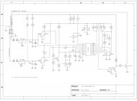
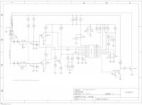
I have not reverse-engineered the "01" board, but have done so on the "01B". I found that someone else has posted a schematic of this board on this forum, and although it was a good start, it wasn't logically arranged and drawn like an engineer would do. So I've redrawn it and added notation for parts, wattage, etc. I'm confident it is correct, but if someone finds an error, please contact me.
By the way, on the dead "01B" board, I found that Zenor diode ZD1 was blown (shorted). Some people on this forum suggested it can be replaced with a generic 12V Zenor. That is probably not true. The correct diode is a 8.2V device, and replacing it with a 12V diode will over-voltage the Hitachi 1825P IC, causing it to at least malfunction, if not die.
About that IC: Lots of speculation about what it is and I, like others, have been unable to find a spec sheet for it. However, the predecessor "01" unit used a Hitachi 17902P, which is a quad op-amp. I suspect the 1825P is something similar. The latter chip has extra pins that are either for heat-sink or extra current capacity.
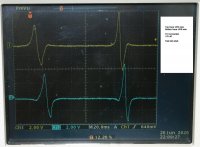
Now for a question: Has anyone put an oscilloscope on the output of the ignition senor coil mounted over the alternator? I've read on this form that the magnets for the sensor can get weak over time. I put my 'scope on the leads and found that the W/G lead produces a waveform that goes ~2.5V negative, and the W/R wire produces a nearly identical, thought inverted waveform, that goes ~2.8V positive. (The B/W wire is the ground reference.) Is that enough to trigger the ignition box, or should I look at newer and stronger magnets?
Hope this information helps someone and they, can in turn, help me.
One of the bikes, a 1981, had the stock, non-function TCI box still attached to the bottom of the battery box, plus another unit tie-strapped on. Someone in the past bought the 2nd box from a junk yard and wired it in to make the bike run. The stock unit is labeled "TCI 12-01B" and the replacement "TCI 12-01", which is part of the story here. I opened both to compare them, and clearly the "01B" is a cost-reduced, later revision of the "01" unit. The "01" version has a more costly double-sided PCB and about twice as many parts, including 7 signal-level transistors (plus the power transistor), whereas the "01B" unit has four transistors and is built on a much cheaper single sided board. I've attached photos of both for comparison.
I have not reverse-engineered the "01" board, but have done so on the "01B". I found that someone else has posted a schematic of this board on this forum, and although it was a good start, it wasn't logically arranged and drawn like an engineer would do. So I've redrawn it and added notation for parts, wattage, etc. I'm confident it is correct, but if someone finds an error, please contact me.
By the way, on the dead "01B" board, I found that Zenor diode ZD1 was blown (shorted). Some people on this forum suggested it can be replaced with a generic 12V Zenor. That is probably not true. The correct diode is a 8.2V device, and replacing it with a 12V diode will over-voltage the Hitachi 1825P IC, causing it to at least malfunction, if not die.
About that IC: Lots of speculation about what it is and I, like others, have been unable to find a spec sheet for it. However, the predecessor "01" unit used a Hitachi 17902P, which is a quad op-amp. I suspect the 1825P is something similar. The latter chip has extra pins that are either for heat-sink or extra current capacity.
Now for a question: Has anyone put an oscilloscope on the output of the ignition senor coil mounted over the alternator? I've read on this form that the magnets for the sensor can get weak over time. I put my 'scope on the leads and found that the W/G lead produces a waveform that goes ~2.5V negative, and the W/R wire produces a nearly identical, thought inverted waveform, that goes ~2.8V positive. (The B/W wire is the ground reference.) Is that enough to trigger the ignition box, or should I look at newer and stronger magnets?
Hope this information helps someone and they, can in turn, help me.