Transmission Roller Bearing Positioning

dps650rider

XS650 Addict
Messages
398
Reaction score
391
Points
63
Location
Pennsylvania
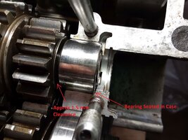
I'm putting one of my engines together and I am hoping someone can answer a question I have long had regarding the positioning of the 2 roller bearings on the transmission shafts. When setting the transmission shafts in the case the roller bearings can be moved back and forth quite a bit, I measured about 1.5 mm on the input shaft. What I have always done is to set the roller bearing so it has a small gap next to the gear (or circlip on the output shaft) and a much larger gap toward the case knowing that as the engine heats up the clearance between the gear and the bearing will increase.

Honestly I don't think this matters since the ball bearings determine the positions of the shafts. There is nothing mentioned about this in the service manuals and I have always wondered if there is a "correct" way of doing this.
 

Attachments

  • 2022-03-09_20-12-30 Trans Bearing Spacing.jpg
    2022-03-09_20-12-30 Trans Bearing Spacing.jpg
    279.8 KB · Views: 145
I'm no expert but I'd be inclined to shim about 75% of that play out of that connection with washers . Why have the ball bearings do all the work combating the sideways motion.
 
I have the same querie and would like to resurrect this thread.
dps650rider did not receive an answer so Im hoping somebody this time may reply.
As dps650rider has stated, the pocket where the needle roller sits allows quite a bit of fore/aft movement.
Refer to number 9 in parts diagram - one on each shaft - shim washer and DPS650rider's photo in the first post.
Why did Yamaha fit a shim washer when you can eliminate any play by simply pushing the needle roller bearing up the shaft and put the crankcases together which would capture the needle roller bearing in that position.
Both the input and output shafts have the same issue and there is no way the 1.5 mm (approx) of play is due to wear.
The only reason I can see where pushing the bearing up the shaft (to eliminate any play) is not a good idea is because the inside edge of the bearing would be overhanging the inside edge of the pocket by a fraction - but this doesnt bother the way the cam bearings sit in their pockets (as an example of bearing placement).
It wouldnt be hard to shim the bearings out, but why didnt Yamaha go all the way and do that from new.
I would like to understand this - hope somebody can help.
I have a motor split with the 2 trans shafts sitting in it if anybody wants any more info.
Kind Regards - Ray.
transmission.png
 
Looking at it from a strictly mechanical viewpoint, you're discussing the caged needle roller bearings, items 10 and 23.
As long as the cage is captured by the case halves, the shaft end is fully supported, it should be OK anywhere as long as the rotating parts are not able to scuff against the cage. As mentioned the key rings locating the ball bearings are limiting axial movement of the shafts.
 
Attached below is the primary Service Bulletin (dated Jan. 1971) covering all models of Yamaha - both horizontal and vertical split cases. It takes a bit of reading, but it covers the side-play issues. The parts diagrams do not show all the shims that may be present (or needed) in a given transmission and it's left to the tech to determine what's required to get proper side-play.
 

Attachments

  • YAMAHA TRANS SERV BULLETIN 1971 259.pdf
    449 KB · Views: 69
RC4Man and JP - thanks for the replies and suggestions.
Ive studied it a bit more and cant decide whether its poor design or clever design.
Input Shaft:
On the input shaft there is .065" between the gear and the bearing (if it is pushed to the outside edge of its pocket)
That gear does not have a circlip on that edge so it also can float .065" fore/aft. I can do this the clever way by just positioning (read shifting) the bearing inwards along the shaft until I have .005" of clearance to the gear - put the crankcase together and capture the bearing in that position. Or I can do it the way I would have thought Yamaha should have - shim it to provide .005" - keep in mind Yamaha have provided a shim in that position, but why for I dont know - maybe as has been suggested to keep the bearing from contacting the face of the gear.
Output Shaft:
The output shaft is a bit friendlier - there is .055" clearance between the gear and the bearing (if it is pushed to the outside edge of its pocket), but the gear is retained on that side by a circlip - so that .055" doesnt effect the running clearance of that gear. Now I have 3 choices - leave the bearing as described above - 2nd leave the bearing as described above and add shims or 3rd slide the bearing towards the gear and leave .005" clearance to the circlip.
I am starting to think its a clever design because it can be as simple as positioning the bearings inwards, leave a bit of clearance and put the cases together.
This is reinforced by the fact that there is no evidence of where the .065 and .055" wear has come from.
JP - yes I have read/studied all of 2Many's bulletins - thanks for the reminder.
Sorry if this has been a bit long winded, but these sort of things do my head in - which is right - which is wrong - it sort of falls into the description of "sloppy" - I'm not a mechanic or trained in any way, so its all learning stuff.
I'm interested in your comments.
Regards - Ray.
 
The shift forks' position is fixed by the shift drum and we're looking for ~75% engagement of the dogs of the sliders in each gear position - with the horizontal cases on the XS, we can test & see that. The mainshaft will be pulled to the clutch side by its hub nut. If we allow the countershaft to have .050" (1.2mm) of side-play beyond spec, does it allow less than 75% engagement? So we shim the countershaft - 1mm would be fine. We might need to shim the mainshaft too if the nut pulls it right to the point that the forks don't have enough travel to engage the sliders fully. The amount of engagement dictates where the shim goes (R, L or evenly split)

On a vertical case engine - where we can't easily assess engagement - a tech should just shim to spec and shim evenly side-to -side

I would not cure excess sideplay by repositioning bearings; would eventual side thrust undo your work?
 
Last edited:
JP - thanks for the reply.
Yes the mainshaft is pulled to the clutch side by its hub nut - also the countershaft is the same, the shaft is pulled to the countershaft sprocket by its nut.
So any play in the shafts is removed by that.
The gear on the countershaft shaft is retained by a circlip - so the position of that gear is constant as far as fork/engagement is concerned.
The gear on the mainshaft can float the .065" depending on where the bearing is located (that gear is not retained by a circlip in that direction).
Taking your advice - I will put the gears, drum and forks back together and shim (if neccessary) to aim for at least 75% engagement.
For the gap between the gear and bearing, on the mainshaft - for safety i will shim out the gap leaving .005" which will position the bearing completely in its pocket/housing.
Thats my plan - thanks to all for your help.
Regards - Ray.
 
Back
Top