MplsMurr
1973 TX650
Hello All,
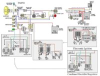
Hope everything is going well with you all. I have designed a new electronics box for my 1973 TX650. I figured that I will be messing with electronics I might as well update. Here we go:
---------------------------------------------------------------------------------------------------
REG/REC COMBO:
I want to update from my separate regulator and rectifier units to a new combo. Now I understand that I can make the $20 separate units with time and all, but I think I want a combo. I was thinking of getting this:
https://www.mikesxs.net/parts/yamaha-xs650-solid-state-rectifier-regulator-70-79
From my understanding of what I read, I have to
Rectifier side (6 space connector)
3 yellow to 3 white
1 red to 1 red
1 green to 1 black
Regulator side (3 space connector)
orange to green
blue to brown
*add 2nd ground from base to bat(-)
**Please tell me if I am mistaken.**
**With that being said, what am I to do with my fuse?**
I am using this thread ( http://www.xs650.com/forum/showthread.php?t=6564 ) as reference, which seems to do a damn good job, but I don't know what to do with the fuse.
---------------------------------------------------------------------------------------------------
STARTER RELAY:
From my understanding, I need something with 30-40 amps and 12 V with 5 pins. Cool. I have seen people reccommend a ford, harley, lawn mower, and headlight relay. If I am not mistaken, the following means it will work for 80 amps and less. Is this correct? I was thinking this looked cool and would fit the criteria.
http://www.ebay.com/itm/26234120290...1&exe=13926&ext=35632&sojTags=exe=exe,ext=ext
My concerns with this are simple. Will it work? Please see image six (6) from the link above, I have NO idea of how I would connect this from my old/current starter relay.
---------------------------------------------------------------------------------------------------
Thank you all in advance! Loving this community and all of the helpful words!
Much love,
Murr.