-
Enjoy XS650.com? Consider making a donation to help support the site.
XS650.com receives a small share of sales from some links on this page, but direct donations have a much greater impact on keeping this site going.
You are using an out of date browser. It may not display this or other websites correctly.
You should upgrade or use an alternative browser.
You should upgrade or use an alternative browser.
Wannabriden's D Port Re-Port
- Thread starter BluzPlayer
- Start date
Latest update...
Cleaned the stock head.
Lapped cleaned valves into the head.
The valve spring compressor I ordered arrived.
My C-Clamp/cut socket works but the new compressor makes it so much easier.
So valves installed. Leak tested.
CC'd...
58.8 on both combustion chambers.
Intake ports...
L-78.2 cc
R-78.6 cc
Difference of .4 cc which is about 1/2 of 1%.
Head is now ready for testing alongside Garrett's D Port once the bench has been calibrated.
The Bench..
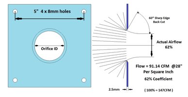
The DP meter and hot wire anemometer have both arrived. Since I am modifying the bench to accommodate the DP meter I also ordered a set of calibrated air flow orifices. They not critical to the bench operations as the emphasis is stictly about the percentage of gains or losses. Still i like to know that the CFMs I will be reading are actual CFMs. Unfortunately the plates won't be here until tomorrow and I can't complete the modification without them. Looks like the bench calibration should be happening Sunday.
Wife's doctor appointment this morning went very well. The latest medications have been making a difference. Still going to be a looonnnggg time for full recovery but she's just a bit better each day. As a result I am able to get a bit more garage time which has been much needed and definitely missed. My Nirvana.
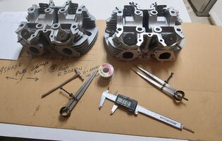
Added some pics..
Nothing you guys haven't seen before..


Cleaned the stock head.
Lapped cleaned valves into the head.
The valve spring compressor I ordered arrived.
My C-Clamp/cut socket works but the new compressor makes it so much easier.
So valves installed. Leak tested.
CC'd...
58.8 on both combustion chambers.
Intake ports...
L-78.2 cc
R-78.6 cc
Difference of .4 cc which is about 1/2 of 1%.
Head is now ready for testing alongside Garrett's D Port once the bench has been calibrated.
The Bench..
The DP meter and hot wire anemometer have both arrived. Since I am modifying the bench to accommodate the DP meter I also ordered a set of calibrated air flow orifices. They not critical to the bench operations as the emphasis is stictly about the percentage of gains or losses. Still i like to know that the CFMs I will be reading are actual CFMs. Unfortunately the plates won't be here until tomorrow and I can't complete the modification without them. Looks like the bench calibration should be happening Sunday.
Wife's doctor appointment this morning went very well. The latest medications have been making a difference. Still going to be a looonnnggg time for full recovery but she's just a bit better each day. As a result I am able to get a bit more garage time which has been much needed and definitely missed. My Nirvana.
Added some pics..
Nothing you guys haven't seen before..
No joy in Mudville....
USPS avoided my house like the plague yesterday. Tracking now says Monday by 8pm.
Hopefully it's a whole lot closer to 8am.
Gives me time to clean the shop...
Fun, Fun, Fun
USPS avoided my house like the plague yesterday. Tracking now says Monday by 8pm.
Hopefully it's a whole lot closer to 8am.
Gives me time to clean the shop...
Fun, Fun, Fun
Did finish taking the physical dimensions for the intake ports on both the stock and d-port head.
Except for the runner lengths which I should have measured before installing the valves.
So they will come back out, get those measurements and reinstall the valves.
No biggie. My valve spring compressor is looking too new anyway.
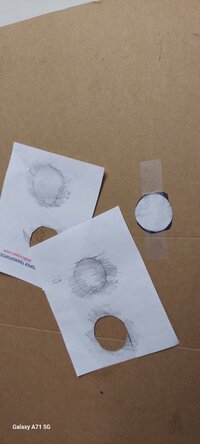
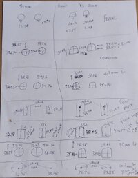
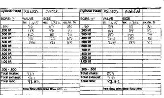
Not wanting to type it all out so just snapped a pic of my worksheet. Hopefully it can be read and followed by those with any interest.
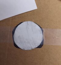
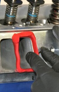
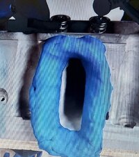
Also did a quick and dirty "transfer" of the port openings, cut a pair out and made a simple overlay. Gives a visual comparison of the change made to the opening. The D port opening is black in the pic. The stock opening is the white circle.
I am planning to graph the other "slices" measured as well but can't find my graph paper at the moment.
On the worksheet the stock head is to the left.
D port to the right . The location description of the "slice" is to the far right on the sheet.
Once I start flowing I will be able to attach values to these "slices" using a probe with an emphasis on velocity as well as identifying the equally important "dead zones" utilizing a probe as well as flow balls. This is done using a 9 point test per "slice". This is part of the port mapping which is tied to the physical mapping just completed.
**NOTE***
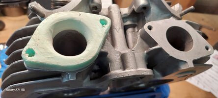
The floor for the D port was only raised
2.56 mm Left
2.48 mm Right
I need to check but it seems that Jack said something like raising the floor 4mm.
Another thing I found noteworthy..
The distance from the opening along the floor to the point where the Short Side Radius (SSR) begins. A few pics..
Except for the runner lengths which I should have measured before installing the valves.
So they will come back out, get those measurements and reinstall the valves.
No biggie. My valve spring compressor is looking too new anyway.
Not wanting to type it all out so just snapped a pic of my worksheet. Hopefully it can be read and followed by those with any interest.
Also did a quick and dirty "transfer" of the port openings, cut a pair out and made a simple overlay. Gives a visual comparison of the change made to the opening. The D port opening is black in the pic. The stock opening is the white circle.
I am planning to graph the other "slices" measured as well but can't find my graph paper at the moment.
On the worksheet the stock head is to the left.
D port to the right . The location description of the "slice" is to the far right on the sheet.
Once I start flowing I will be able to attach values to these "slices" using a probe with an emphasis on velocity as well as identifying the equally important "dead zones" utilizing a probe as well as flow balls. This is done using a 9 point test per "slice". This is part of the port mapping which is tied to the physical mapping just completed.
**NOTE***
The floor for the D port was only raised
2.56 mm Left
2.48 mm Right
I need to check but it seems that Jack said something like raising the floor 4mm.
Another thing I found noteworthy..
The distance from the opening along the floor to the point where the Short Side Radius (SSR) begins. A few pics..
Attachments
Last edited:
Finally. On the late side but in possession and looooking goooood....
Wife has a doctor appointment first thing in the morning, then I'm out in the shop to complete the modifications and reassemble the bench. Testing on Wednesday at long last!!!!!
Wife has a doctor appointment first thing in the morning, then I'm out in the shop to complete the modifications and reassemble the bench. Testing on Wednesday at long last!!!!!
Attachments
Hugh didn't care how the head was mounted for the accurate angled when he placed it on the milling machine, as a result,
more was machined at the port floor gradually going up towards the short side like a ramp. At the port endurance, the floor-to-roof
height should be in the neighborhood of 30MM and at the short side up 4mm. Later on, I'll take measurements of the port's short side
wall-to-wall.
more was machined at the port floor gradually going up towards the short side like a ramp. At the port endurance, the floor-to-roof
height should be in the neighborhood of 30MM and at the short side up 4mm. Later on, I'll take measurements of the port's short side
wall-to-wall.
Sounds great Jack.
Information is what this thread is all about.
It's a blessing to have someone with your experience to help provide input.
On track to calibrate the flowbench tomorrow.
Then we are going to flow some heads..
Establish baselines for Garrett's D Port as is as well as a baseline for the stock head which has simply been cleaned with stock valves lapped and sealed. The same treatment as the D Port.
Once the data has been collected I will be removing all of the epoxy from Garrett's D Port and cleaning it for reconstruction.
The stock will take a different direction.
I will be flow testing small changes (simply cleaning up the port casting for example) and valve grinds/mods. It will be retested after each modification. Everything will be shown.
This will not be a thread with me simply reporting numbers. Testing for both heads will include:
9 point flowball (turbulence & dead zones)
Performed at each "slice/half slice"
9 point velocity
Performed at each "slice/half slice"
Velocity at port side of valve
Clocked in 9 positions
Smoke tests
Used to indicate swirl.
Obviously CFMs as well.
The intention is to be intensive and extensive.
From mild to wild...
Members can see the numbers.
They can see how the tests are done.
They can decide what is worthwhile for themselves and their machines.
I invite input....
Additionally I will opening up the junk head (that gggGary was kind enough to donate for the cause) to see just how far it can go.
I will post those numbers as well.
My plan at the moment is to mold the port using that very opened up chamber utilizing clay (much easier to manipulate and change.
There are a number of port designs I will be looking at beyond the D Port. I will say that I expect the D Port design to be on the leaderboard. These big ports beg for the increased velocity this design brings to the table.There are other ways to try and achieve that same goal and I will be exploring them as well.
Garrett's head will be designed for a 700cc bike running a Shell #1 cam. There is some math used to match port design to specific engines and their use. I'll touch on it at the time if there is any interest. There are also "markers" that are targeted values we will be trying to match.
These values are widely recognized standards.
Much of what I know I have studied from Smokey Yunick (If you don't know, you don't know. If you do, you do) as well as David Vizard. Ditto from above. There are others but those two have been and by many are still considered mountaintop guys. Having someone here like Jack who truly gets it... that has spent innumerable hours studying, testing and modifying these specific heads is an incredible asset for this community. Furthermore, his willingness to share his knowledge in his Epic thread has been inspiring to myself as well as others. The gains he made are undeniable.. (remember, it's ALL about the PERCENTAGES)
The head he created for @spungle received VERY high praise when driven. Seat of the pants I know.
But I always say,.. if your pants in the seat can't tell difference ... well....
That's where it matters isn't it?
Enough typing.
Work to get done so I can get this party started.
Last edited:
Bench is COMPLETE!
The epoxy dried enough to drill, etc.
However with the pressures I pull I decided not to run it for testing today to allow the epoxy to actually cure (even though the epoxy is not in the direct airflow). Was VERY tempted as I am anxious to see it in action, but no need to tempt fate and create another setback.
No doctor appointment in the morning so that means the long awaited (by me anyway) qualifying/calibration of the bench in the morning... Head testing in the afternoon!
There will be video.
Did get a few other peripheral things done.
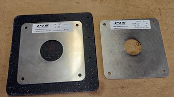
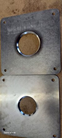
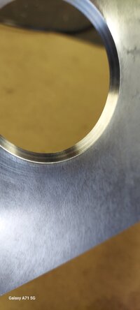
The sharp edges on the intakes cause havoc with the air so the standard is to use rolled clay to create a radius edge to smooth the flow. The issue I see with this is that it isn't consistent. So I made some bolt on plates for testing which will be far more consistent for all testing. These really need another layer of hardening (actually a specific liquid nails) but are ready for testing except for final shaping/sanding which will only take a few minutes.. I'll upgrade them later without changing the radius. The D Port requires one specific for each side. I will make the right side first thing in the morning before calibration so it has time to dry for testing.
The sharp edges on the intakes cause havoc with the air so the standard is to use rolled clay to create a radius edge to smooth the flow. The issue I see with this is that it isn't consistent. So I made some bolt on plates for testing which will be far more consistent for all testing. These really need another layer of hardening (actually a specific liquid nails) but are ready for testing except for final shaping/sanding which will only take a few minutes.. I'll upgrade them later without changing the radius. The D Port requires one specific for each side. I will make the right side first thing in the morning before calibration so it has time to dry for testing.
Attachments

I would be grateful for any details on milling out the intake. I thought I had it sorted by reading Jacks D port thread but now I am not so sure.
I am enjoying this thread immensely thank you.
I have the same valve spring compressor as you and did a few mods to improve it. I will post details in the home made tools thread, to avoid clutter on this thread.
I am enjoying this thread immensely thank you.
I have the same valve spring compressor as you and did a few mods to improve it. I will post details in the home made tools thread, to avoid clutter on this thread.
Bench is up and running.
Did some calibrating...
Some head testing tests...
Here is a video giving a bench overview.
Need a second camera to actually show the process so that is coming tomorrow.
I have my cameras charging and tripods ready...
I will say I am very pleased with the bench's operation.
You can see the video Here.
Last edited:
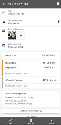
The test probes create a nice report which I am of course just getting acquainted with.
Attached is a screenshot of one of the tests ran earlier today as an example.
They provide much more information than this examples shows.
All the data as well as the averages etc. including graphs.
Hope to be able to show the software in action tomorrow.
One other note...
The valve adjusting fixture bolts are too short for me to get full lift.
I will be replacing those in morning prior to testing.
Attachments
You are not the only one looking forward to tomorrow. This is a great thread I am very much a novice and I am learning a lot.
Keep up the great work.
I use a cheap 10kW light dimmer mounted next to the vertical manometer to control the motor speed .
A light dimmer will work on vacuum motors as they are series motors.
I did have a brain wave about reversing the vacuum motors to do exhaust ports but was told the fans were very inefficient when reversed so made the vacuum box reversible instead.
I have difficulty reading the inclined manometer (mine is mounted across the differential plate) so very interested in your digital one.
Videos are processing now.
Posting tonight once complete.
VERY pleased with the results....
Posting tonight once complete.
VERY pleased with the results....

Finally!
You might want to turn down your speaker...
Video is looonnnggg.
But I wanted to leave no room for doubting the accuracy.
Hopefully a few of you will find it interesting.
I'll be fully testing both the stock and D Port head over the next two days.
Hoping to demonstrate some of the testing not yet covered.
Added a couple of attachments as well.
Here is the video..
Attachments
Thanks for sharing. You've done a LOT of work! can't wait for more!
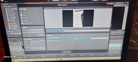
You might want to look into video editing.
You might want to look into video editing.
You might want to look into video editing.

Ha Ha
I think it had more to do with the Flintstone computer I was using....
Like the old Pat Travers song " Crash & Burn".
Guess it's an indicator that I should get something from this millennium.
Apparently I have taken my "vintage" affliction too far.

Bravo, great result!. You are inspiring me to get back to my bench and stop fiddling about with fibreglass.
I have found that it can be tricky adjusting to get 28" with small valve openings but gets easier as the valve opens up.
I have found that it can be tricky adjusting to get 28" with small valve openings but gets easier as the valve opens up.
Thank you for taking the time to get your flow bench up and running, it looks great. The numbers I gave were off a calibrated superflow
and hats off to you for backing me up and showing that my numbers weren't sugar-coated nor was I bench racing as one person suggested.
The D port when done correctly will flow big down low and right through the whole flow curve with increased velocity. You're going to enjoy
that new tool and hopefully make some $ on the side.
Similar threads
- Replies
- 15
- Views
- 927