PHASE 2 THE REWIRE BEGINS
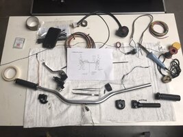
I have now assembled most of what is needed for the rewire and M-Unit installation.
I also purchased a few quality tools that I did not own such as IWISS Crimpers / Wire Stripping / Ferrule Crimpers.
My Dads 50 year old mains plug-in soldering iron whilst still functional has its limitations. So I invested in this:
View attachment 220386
A butane powered soldering tool of great versatility. Its also easy to use around the bike due to not having a lead to drag around. Having used this for the past two days I can highly recommend it.
The other items I have bought are MOLEX MIZU P-25 Waterproof Mini-Connectors in various sizes:
View attachment 220387View attachment 220388
As you can see above the size comparison allows easier positioning for joints that need to be separated; or routed through confined areas.
For example I have used these on the M-Gadget Blaze Handle bar Indicators. It means in the future I can disassemble the flashers without having to de-wire the whole internal handlebar loom (If it was hard wired you would have to). Again highly recommended.
Now onto the rewire.
I had previously removed all the handlebar controls & grips and offered up the M-Gadget indicator to the bar end.
Imagine my surprise when the indicator wouldn't fit down the bar end! The 14mm ID was short on depth.
View attachment 220389 View attachment 220390 View attachment 220391 View attachment 220392
I had to buy a new 14mm HSS bit to fit my drill. For some reason they are called Blacksmiths Bits when over 12mm?
Bar ends were drilled out to the maximum depth the drill bit would go; in order to accommodate not only the indicator assembly but also the M-Gadget Mo.Button. Other holes were drilled into the bars in accordance with M-Gadget instructions. This does mean re-installing all the handle bar furniture and Revival Momentary switches to mark out the holes for the internal wiring.
Then set about it with the Auto-Hole punch (Brilliant tool) and 6mm drill bit.
View attachment 220393 View attachment 220394
As usual always use a little cutting fluid when drilling metalwork.
Once all holes were de-burred (another new tool) and swarf blown out of the bars the wiring could begin.
Now if you intend on doing this yourself allow plenty of time because its is a real FAF! (Fuc*ing Awkward Fiddle!)
My eyesight is not what it was in my twenties; and finger dexterity has also suffered to an extent. Coupled with the Revival terminals in the switches you need a watchmakers patience and skill. Yes the air was blue at times. Using some thin solid wire makes the process of poking the various wires through a little easier.....but its still frustrating! Then if you follow M-gadgets wiring plan you have to get half of the M-Buttons wires across to the other side of the bars to reach the other switch cluster.
Only to find the wires are too short to reach through and across my tacker bars! So strip it all out again and re-think.
I didn't want to extend the wires, so I decided to put the M-Button in the bottom center of the bars, and splay the wires out to each end. I created an elongated hole in the lower section of the bars, and drilled a hole through the top yoke to feed the green 'can-bus' wire and common ground wire, together with the front indicator feeds, back to the M-Unit located under the seat. The elongated hole allowed me to push the M-Button up into the bars. Tip here, connect all the grounds together, it makes sense and means only one ground wire exiting the bars.
View attachment 220397View attachment 220398
During this process I also fabricated and fitted a bracket to hold the M-Gadget Speedometer.
View attachment 220403
View attachment 220404
View attachment 220405
View attachment 220406
Once the kit was installed I tested how it worked by rigging up a power feed and ignition feed to the M-Unit; not forgetting the ground. The M-Unit went thorough it auto-check procedure and looked ready to go. Press a button on the bars and....Nothing!
Checked the other side switches and.....Nothing! Lots of swearing and pulling out my hair! Calm down have a cup of tea then come back and check all connections again. I did find a weak joint on the ground wire; re-soldered and back to the buttons. Bloody hell everything is working.
View attachment 220407
When you step back and look at the bars in their wire free minimalist state you do notice other things. The main one for me is how UGLY

the brake reservoir looks. I hadn't really given it a second look before; but it has to go and be changed for something far better.
What I did learn is that the M-Unit is sensitive. All connections MUST be secure and especially any ground connections.
Having good quality tools made a big difference to the installation and the enjoyment in doing it; compared to the cheapo wire strippers I used to use (now scrapped). A selection of Tweezers and prongs also aid in pulling the wires through little holes.
Don not underestimate the time it takes to do this.
Next job is to finish the ancillary wires to lights and the speedo' unit Etc.... Then on to the Ignition part of this system.
All the best
Ads.