Winter project: upgrading time! (R6 forks and more...)

My nut collection is sorta getting out of control... After a 15-5 stainless, a aluminium and a steel one, the latest is titanium. Because. titanium.

tita.jpg
nuts.jpg


And the last one for today, something Non CNC haha. Made a luggage rack, pretty thin walled tube but i think it came out really nice! weighing in a 700 grams.

lug 1.jpg

lug 2.jpg


Next up: shaping the seat foam!
 
Last weeks ive been working on the seat, the electronics and the final details.

Spend quite alot of time finding the right kind of foam. And determining the thickness and shape. Really hard and time will tell if the ergonomics have been improved.
IMG_20210508_125355301_HDR.jpg

IMG_20210510_203725506.jpg

IMG_20210529_110109571_HDR.jpg

The upholstery guy did a nice job on the cover!

After that I spend most of the time on the electronics. Something I'm not the biggest fan of. I did a lot of research about the way they wire racing cars, aviation and military specifications. Some how I find that really interesting.

If you are interested here is a great source of information:
https://www.rbracing-rsr.com/wiring_ecu.html

My goals here are:
- completely new loom.
- highest spec. For normal money
- no soldering unless I have no other option. I did everything with open barrel crimp splices because they offer the most reliable connection.
- document everything

I considered going for an M-unit but found it to expensive, thinking I could save money just buying separate components like wires, terminals, connectors and relays.
Turns out this was quite more expensive than I would have thought. Doing it again I probably would go for an M-unit. Although I did learn tons from this!


First thing I did was spend quite some time with PowerPoint drawing the new schematic.
XS 650 wiring diagram V3.0 highres.png


This is what I came up with. Please feel free to review this!!!

I wanted to add things like a horn and indicators because I really missed those. Secondly I wanted to run thing through relays because last year I had quite some issues with weird backflow stuff.

IMG_20210520_190345770.jpg

Next I got automotive grade wiring (mill. Spec I found to expensive), components like switching gear, shrink tubing, splice crimpers and tons more.
 
Got this one from domino, real nice OEM like unit. It has all the functions I wanted.
IMG_20210520_185155776.jpg


I rebuild the kill switch
IMG_20210522_104604470.jpg


I tried to find a lot of info online before I started my wiring. Just gonna post some details here if anyone else might be looking for this in the future.

Here is an example of the open barrel splices and raychem SQL shrink tube I used.
IMG_20210525_120958967.jpg

IMG_20210525_121301091.jpg

IMG_20210525_122858085.jpg


Got a new regulator and used a FEP automotive connector here
IMG_20210527_154404735.jpg


Getting the routing right was a pain. Especially because after you crimp or splice there is no way of fitting shrink tube anymore.
IMG_20210601_155739328.jpg


The battery box and headlight became very cramped with stuff. I tried to not over-connector things but never getting them apart is the other side of the coin.
IMG_20210601_173826583.jpg

I tried to label as much as possible, to help out the next guy in case there a problems. The next guy is probably me.
 
Something I learned about labeling is that Dymo sells industrial labels. These adhere much better than the stock ones. They tell you they can only be printed with the expensive industrial label makers. Turns out the cheapest model works to!
IMG_20210525_172600041.jpg


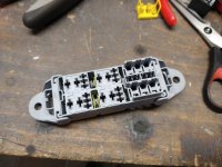
Some details about the power distribution of the fuse box.
IMG_20210528_133033855.jpg

IMG_20210528_133345177.jpg


IMG_20210528_135802450.jpg


IMG_20210528_141827242.jpg


The ignition switch I got had open terminals on the back.... Quite strange. Made a cover for it:
IMG_20210602_144724745.jpg


A lot of hours later, everything is in place!
IMG_20210605_104018062.jpg
made an insulated ground bar for the sensitive stuff like the TCI ground. Tested most of it on the bench and it looks like most of the functions are working!

Super happy so far.

Yesterday I took the bike outside and tested the rest of the bike. Hoping it would run.
IMG_20210605_113915713_HDR.jpg

It did! And I really like the looks of things.

Here is a detailed video of my new rearsets in action:
 

Attachments

  • IMG_20210528_131311534.jpg
    IMG_20210528_131311534.jpg
    161 KB · Views: 76
The only thing is, I haven't ridden it yet because the bike is running but not charging.... Bummer...

I'm trying to find out why. I've followed gggarys great topic about the charging system (thanks form that Gary!) And this is what I know:

- battery holds charge at 12,6v
- getting 12,55 v at the browns rotor brush wire.
- not getting magnetic field though... (Checked with feeler gauge)
- brushes long enough and springs are decent.

Now this rotor is a rewound one I got last fall.... But I believe something is going on with it. It did charge when I put is away for the rebuild. I measured the resistance between the slip rings with the brushes removed: around 4 ohm . Although I found the VOM to react quite sluggish and slow....

No contact between either ring and ground.

Jumped battery voltage straight to the brushes with the R/R disconnected, still no magnetic field
IMG_20210606_151728603.jpg

Could this rotor be bad at 4 ohm? Manual states 5-7ohm. I checked this value with both of my VOMs.

I could make a new topic for this issue, but if someone has an idea, I'm all ears. Just want to go riding!!!
 

Okay maybe its more like 3,8 ish. Forgot to subtract the leads.

So even if the resistance is a bit lower than spec. It should still produce a magnatic field and charge some? It's charging nothing. Just reading batt voltage on the dash.
 
Maybe I was expecting a pretty strong magnetic field and used to thick of a feeler gauge. Just retested and now it looks like a got a magnatic field!

Could this mean my R/R is not working correctly or hooked up wrong? Since the ground of the brush run thru that.

It's a new unit and I did indeed not run it before....
 
Yeah I jumped the brush to ground in the video.

I just checked the ground of the R/R, seems ok. It ran to the original ground point next to the battery. Just now I put it straight on the battery negative. Didn't make the rotor magnetic by itself.

IMG_20210606_200138137_HDR.jpg


Here you see that small think wire of the batt neg to the ground point on the frame.

The engine has three of these:
IMG_20210606_200200034.jpg
 
What an amazing amount of work you have been up to! Well done! Your bike started up nicely, is that the CARMO's strong spark?

The wiring diagram looks fine and I cannot see an issue with the R/R wiring which is correct for a Type A regulator i.e. the regulator controls the connection from the brushes to ground.

I wonder why the Pass Switch? I think that is the middle setting on the Lights On/Off switch. Is it just to flick the headlights to Hi when overtaking during the daytime when riding with lights Off? On my Virago I have left it unconnected because I don't know what to do with it. Perhaps it can be used to have all indicators flashing when stopped in an emergency, or all indicators fully on when driving without headlights??? I don't think it is on when the headlight switch is in the On position so does not appear to offer anything at night. Its purpose is a mystery so I figure I am missing something. Maybe someone will explain it to me - Thank you in advance.

Thanks!
It's a Carmo ignition indeed. Haven't run it enough to tell is its reliable.

Well the pass switch is the only thing I didn't really need. But domino only make certain configurations of switch gear. I wanted a possibility to turn the lights on or off. That middle settings btw, is for parking lights.
 
O I just checked: the bike is charging when I jump the green wire to the battery negative!!

Did notice on the instrument cluster where the voltmeter is, that with this jumper the voltage does go down to 11,8 v with a non running engine. With the engine running it went up to more than 15v so I only tested it for a couple of seconds.

Can I conclude my new regulator/rectifier is broken?
 
So I found a topic where pamcopete described how to measure a late type regulator/rectifier.

Measure between red and all the white wires. One way should have resistance, reverse the leads and should see no continuity or very high resistance.

Repeat with the black wire to the 3 white ones.

IMG_20210607_103449641_HDR.jpg


I just did this test with all the 3 units I have. Put the VOM on diode mode and see that all three units test in a similar fashion.

Red -white: all around 0.5v reverse the leads, no continuity.

For black to white the results are inverted.


Additionally I checked the resistance of the green brush through the wiring to the R/R connector. I get low resistance.

What's going on?
 
Thanks for the comments. Regards the R/R, maybe it is faulty, or were you supplied with a Type B by mistake? Do you have a Type A from an XS Special you could check against?
 
Coming back to my previous post about checking the R/Rs I have. I think what I'm measuring is the rectifier part! That seems to work. That would explain why with the new jumped it's producing a DC voltage of more than 12v. However I cant measure the regulator bit...


I just hooked up one of my older R/Rs. With this in place it is charging to 14,5 v. However two things I noticed:

- With the old R/R it's not running a smooth idle (with the new R/R it is.
- there is a big voltage drop at the brown brush with the old R/R from 12,6 to 12v. With the new this is only from 12,7 to 12,6.
IMG_20210607_115352295.jpg
 
Back
Top