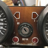
I was in the process of jetting a set of Mikunu vm32s when I noticed a drop in idle speed each time I slowed to a stop. Initially I suspected a fuel related issue, but found it happens each time the front or rear brake is applied. I started to poke around and noticed more strange electrical behavior:
- I think this is actually normal and not relevant: the flasher relay clicks when the key is turned to 2nd position (where 1st position is off)
- Not relevant: flicking the flasher relay unit will cause the lights to flash when the flash switch is toggled on
- FIXED (the bulb's ground and hot were both plugged to ground): when the flash switch is toggled on, the flashers are solid except for the right front. The bulb in this position is good
- FIXED (caused by undercharged battery/operating without running motor): when either side of flashers are on, they will flash once each time the brake is applied (stop light illuminated)
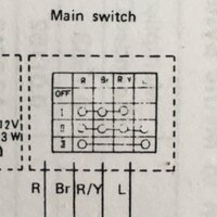
- FIXED (the brake lining indicator and oil pressure warning bulbs were switched): when the ignition is in 3rd position, the brake lining indicator lights and no flashers will light at all
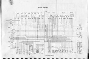
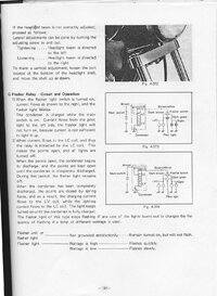
I have a multi meter but no idea where to start. The manual says solid flashers indicate an unsatisfactory ground. Anyone have any pointers?
- I think this is actually normal and not relevant: the flasher relay clicks when the key is turned to 2nd position (where 1st position is off)
- Not relevant: flicking the flasher relay unit will cause the lights to flash when the flash switch is toggled on
- FIXED (the bulb's ground and hot were both plugged to ground): when the flash switch is toggled on, the flashers are solid except for the right front. The bulb in this position is good
- FIXED (caused by undercharged battery/operating without running motor): when either side of flashers are on, they will flash once each time the brake is applied (stop light illuminated)
- FIXED (the brake lining indicator and oil pressure warning bulbs were switched): when the ignition is in 3rd position, the brake lining indicator lights and no flashers will light at all
I have a multi meter but no idea where to start. The manual says solid flashers indicate an unsatisfactory ground. Anyone have any pointers?
Last edited: