sleddog83
XS650 Addict

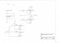
Here is the TCI test jig I have been using. I have included the arduino code, in case any one wants to tinker. Also included is a schematic of the extra circuits I created to get it working. You would also need an oscilloscope to view the waveforms. The jig generates the two pickup pulses for the TCI board and a TDC pulse to help sync things on the oscilloscope. The pushbuttons allow you to increase or decrease the RPM. The jig is useful in repairing, testing and modifying TCI modules. It provides very stable pulses, that make it easy for scoping the ignitor boards. There is still a little problem with switch bounce but that may be just the cheap switches I used. The arduino board I used is a Arduino UNO but you could likely use just about any arduino. Part of the extra circuitry is on a proto shield underneath the pushbutton board. The LCD is extra. The program will also send out messages to any serial monitor. I might include a video someday if i can ever master my camera.

")