smokestacks
XS650 Member
have a 78 motor with Pamco standard ignition with a stock advance unit, sparx capacitor, and am installing a new HHB PMA on it, as PO had fried the old stator, and I wanted a fresh start.
I got it fired yesterday because I hooked it up to my old harness, but it was not regulating. It would idle at 11 or so and then when revved, shoot up to 15 and blow my headlight before i would kill it in fear of frying everything. I know all my grounds are ran properly. they are all grounded to the back of the coil mount screw(unless this is my problem and a shit place to ground), and they are all tied to the engine at the cam chain tensioner as an extra motor ground too.
The regulator/rectifier i got with my kit has the 3 standard yellow wires that go to yellow on stator......check......red goes to positive on cap....check.....ground reg to frame...check......there is not mention of the green wire from the reg in the new instructions. In the old kit, green went to ground and the online tech for PMA install says the same, so I assumed it was the same case.....i messaged Hugh and he said red is 12v+ and green is 12v-.this has me stumped. so would connecting the green to ground on this new unit send positive signal through the ground as 0-(-12) = 12? Do I not use the Green on the new one?
Could my capacitor be bad even though it starts up and runs? and that's what is sending the surges to the rest of my stuff on accel?
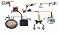
This is my wiring diagram. forgive the crudeness, as i made it in paint.
I got it fired yesterday because I hooked it up to my old harness, but it was not regulating. It would idle at 11 or so and then when revved, shoot up to 15 and blow my headlight before i would kill it in fear of frying everything. I know all my grounds are ran properly. they are all grounded to the back of the coil mount screw(unless this is my problem and a shit place to ground), and they are all tied to the engine at the cam chain tensioner as an extra motor ground too.
The regulator/rectifier i got with my kit has the 3 standard yellow wires that go to yellow on stator......check......red goes to positive on cap....check.....ground reg to frame...check......there is not mention of the green wire from the reg in the new instructions. In the old kit, green went to ground and the online tech for PMA install says the same, so I assumed it was the same case.....i messaged Hugh and he said red is 12v+ and green is 12v-.this has me stumped. so would connecting the green to ground on this new unit send positive signal through the ground as 0-(-12) = 12? Do I not use the Green on the new one?
Could my capacitor be bad even though it starts up and runs? and that's what is sending the surges to the rest of my stuff on accel?
This is my wiring diagram. forgive the crudeness, as i made it in paint.