Good Vibrations..

A few more things to chew on....
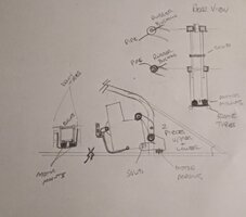
The dogbone's only purpose in life is to stop the engine moving aft under power, so logic would say have it exactly parallel to the top chain run. But if you dig deeper.... the torque is also gonna make the engine (try and) rotate opposite the sprocket. The top of the engine will want to rotate aft and the aft end of the motor will want to rotate down. So, if we angle the dogbone down on it aft side slightly... as a guess 10-15°... with the front pointing up, it will tend to offset the torque rotation. Of course.... that's gonna feed more vibes back into the frame.... so this is a game of tradeoffs.

More chewin'....
Norton made the engine/swingarm combo partially to hold the sprockets in alignment with each other. As we are ponderin'... there's nothing there to do that. You might need another dogbone to offset that. One that mounts horizontally and goes left to right..... to stop the engine from wiggling left and right, moving the sprockets out of alignment. So again... as close to the sprocket as possible.

...and yes, I've done a lot of ponderin' on this over the years.
 
Last edited:
Volvo alternator mount bushings Might be useful.
1652247746807.png1652247801914.png1652247927320.png
 
After some contemplation on @Jim 's knowledge I have made some more changes to the game plan. I feel like it is much closer although I am certain it is not finished yet. @Team Junk 's contribution had me thinking more about my original ideas which had yet been fleshed out and were completely inadequate. However digging back into the inspiration for the mod it is indeed bushing similar to those presented by TeamJunk that they used as an isolator/bushing on the swingarm pivot arm.
As Jim said there are trade offs no matter which way I go with this. Absolute performance screams out for solid mounting. Lessons I learned as a very young man building street racing cars. The intent is for this build to be a performer but as a hardtail, not the highest performance. The consideration is dampening and the engine mounts are only a PART of that equation. The hopeful end results will be a culmination of several factors. One of the primary factors being the engine balance and rotating assy runout. Sorry slipped a bit of the subject at hand.
The studies I have done so far in researching the machines that use this (actually just similar) idea focus primarily on limiting/eliminating the engine's movement left and right. They also took steps to keep the sprocket distance static to the rear wheel by incorporating the rear motor mount cradle with the swingarm pivot.
These key points have been pointed out by Jim and something I took a hard look at. However it appears to me that there is some rocking between the sprocket and rear drive at that swingarm pivot since it has rubber bushings where the engine mount cradle and swingarm mate.
Not too much is my guess since that design works. So the plan is to hold it solid left to right while attempting to allow no greater rocking than the Norton/Ascott design. I am attaching a crude drawing attempting to illustrate what I have in mind.

In this iteration the rear motor mounts will be in two pieces which connect as follows.
Utilizing the two through holes in the central down tube (which were used for the upper rear motor mount) in a design similar (yet not) to the original top motor mount.
Due to the 15 degree tilt of the engine the triangulated mount will have to be stretched to reach the upper rear engine mounting holes.
Solid mounted to the frame but at the engine point there will be a tube welded which will house the bushing. Bolted through from one side to the other limiting left to right movement while dampening the vertical forces through the insulating bushing.

The lower half of the rear mount connects like this.
This is still what I would call a motor mount "box" as the pieces are boxed for additional strength.
Anyways...
Solid mount to lower rear engine mounting holes. The bottom of the box mounted to rubber motor mounts which are connected to the frame through a lower plate welded between the frame rails. The upper mounting point on this lower motor mount section is attached to the lower of the two central down tube upper rear engine mounting holes.
It will also be welded to a pipe housing a bushing like the upper section as described above.
Both sections will be attached to this point. The upper sandwiched between the lower and the central down tube. Hopefully you can follow along on the drawing.

The drawing also shows some of the ideas for the front mount but I am not addressing that at this moment unless someone sees something blatant that I should look into.
Again any and all constructive or thought provoking ideas or pointing out issues or concerns are invited.
It is only through those kinds of comments and links that I have gotten this far. It is appreciated.
 

Attachments

  • 20220511_213119~2.jpg
    20220511_213119~2.jpg
    131.6 KB · Views: 87
Back
Top