Basically you have an early mount now.
-
Enjoy XS650.com? Consider making a donation to help support the site.
XS650.com receives a small share of sales from some links on this page, but direct donations have a much greater impact on keeping this site going.
You are using an out of date browser. It may not display this or other websites correctly.
You should upgrade or use an alternative browser.
You should upgrade or use an alternative browser.
Good Vibrations..
- Thread starter BluzPlayer
- Start date
This is a very interesting conversation.
Yes the lower triangle in my opinion should be adequate as well. Obviously many people have run them without the top mount. Some have ended up putting them back in after feeling the handling slip somewhat according to their reports. That can well be a function of riding style, especially if combined with other modifications as well. My thoughts on the front mount were similar to what you have shown except my brackets would have been to the outside of the frame which would open the spacing between the mount and the engine for the rubber isolators to fit. Additionally I intended to add steel bars in the opening between the frames to keep the front structure stiff. Eliminating that bracing across the downtubes is somewhat mitigated by using the engine to tie the frames together. Utilizing the rubber isolators as I had intended more than likely would have created an issue without adding back the bars as described. It still would have been an improvement visually over the stock block and may have provided cleaner air flow to the front of the engine as well. I'm enjoying following your mods and am looking forward to seeing results from the road testing once you get to it.
takehikes
XS650 Addict
I’m looking hard at the very least getting rid of the tube between the neck and top mount. Bugs me how ugly it is. if all goes as planned (never) I’ll be raking and putting new side neck plates on it that may be the moment to get rid of it.
if all goes as planned (never) I’ll be raking and putting new side neck plates on it that may be the moment to get rid of it.I will be replacing the the side neck plates as well as the tube. Won't be removing it but modifying as I will be using that for the new location of the top mount once I tilt the engine 15*. I am hoping the tank I have selected will have a deep enough tunnel to cover that area. I am hoping to start stripping the frame next week.
Other things going on so we'll see.
I have thought about raking the neck but I have just too many things going in the build now and have no desire to add more problems to solve.
It seems that once I am finished, about the only things on the bike that will be stock will be the mag wheels, the cases, and perhaps the charging system. Maybe something else will make the cut.
takehikes
XS650 Addict
The Xs650 has a steep rake and when going with a hard tail it looks awkward to my mind If you don’t rake it. After my hard tail was on mine sits around 31-32 degrees. 40 would look much better and is kind of a sweet spot for choppers. I’m leaving the stock front end (no fender, XS1100 disc moved to left side so can’t be seen as well when parked).
Sounds very interesting.
Do you have a build thread?
I'd love to follow your mods.
Although my bike is hardtailed, I'm not really going for the chopper style.
More like a bobber I think.
Bigger beefier front forks. Twin discs.
All from the R6.
The build is called the "Punisher" so svelte probably won't cut it.
Do you have a build thread?
I'd love to follow your mods.
Although my bike is hardtailed, I'm not really going for the chopper style.
More like a bobber I think.
Bigger beefier front forks. Twin discs.
All from the R6.
The build is called the "Punisher" so svelte probably won't cut it.
takehikes
XS650 Addict
Don’t have a build thread but may put one together. Here is something I’m playing with on side of battery box…… worked perfect for forward controls…..hacked up stock brake pedal, bent up brake arm, Heim joint to custom brake rod ……note TCI unit on back of box, also box on rubber mounts.Sounds very interesting.
Do you have a build thread?
I'd love to follow your mods.
Although my bike is hardtailed, I'm not really going for the chopper style.
More like a bobber I think.
Bigger beefier front forks. Twin discs.
All from the R6.
The build is called the "Punisher" so svelte probably won't cut it.
I think you should.Don’t have a build thread but may put one together.
You have several interesting and outside the box ideas.
Love getting additional use from the battery box. I don't have a TCI but will most likely be using some form of crank triggering ala "Gonzo" modified for the rephase. Possibly using aurdino to program the advance curve. You are clearly ahead of my progress as I am only now about to strip my frame.
A THINKING man!Don’t have a build thread but may put one together. Here is something I’m playing with on side of battery box…… worked perfect for forward controls…..hacked up stock brake pedal, bent up brake arm, Heim joint to custom brake rod ……note TCI unit on back of box, also box on rubber mounts.View attachment 212115
Love it.
Ok.
No turning back now.
I've started stripping the frame.
Beginning with the peg bungs, the lower motor mount bolt throughs, the side stand nub, and then the lower rear motor mount wrap around from the the central down tube. Everything still needs cleaned up but with everything out of the way my mind was free to visualize how to approach the problem. The front mount isn't so difficult as I have been able to see enough pictures of it to have a solid understanding of how to approach it. That section is made even easier thanks to @Jim 's work with his modification integrating a motor mount.
Feeling good about the front mount's solution I have focused on the rear mount. Hard to find clear pics about how it was addressed on the Halco Ascott, so I took a path studying the bike which inspired Bob Trigg and the rest of the team in their foray which ultimately resulted in the Halco Ascott TT. Based on Triggs work with Norton and their isolastic motor mounts.
Unfortunately that information wasn't directly related as it was a swingarm design.
My bike (The Punisher) is a hardtail.
The engine cradling concept was the key element I gained from studying that design.
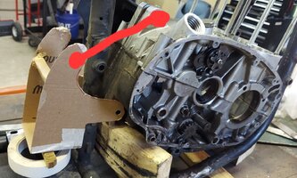
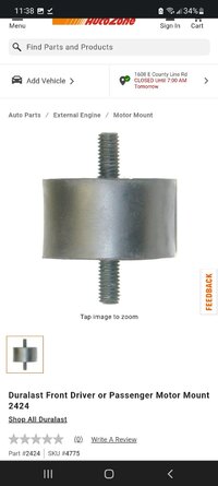
Anyways this is a work in progress so bear with me as the design goes through it's various stages. First I blocked the engine at approximately the 15 degree forward tilt I am looking for. I started making templates from cardboard. This is the 4th iteration. Anyways the idea is to have a pair of rubber motor mounts between the bottom of the "motor mount box?" and a crossmember plate across the bottom of the frame behind the central down tube. The "motor mount box?" is bolted through the lower rear mounting holes on the engine and to the two rubber motor mounts at the bottom of the "box" connected to the crossmember plate. To prevent the box from rocking on the lower rear mounting bolt as a pivot, the rear upper mounting bolt must also be used (following the engine cradling concept). This connection will be made using a torsion bar style setup utilyizing helms joints.
(See the red line in the pic).
This design will give me additional versatility in tuning the forces loaded onto the mounts.
Long ways to go but the direction is set.
FORWARD.
I need to finish stripping the frame gussets etc and clean up the frame before proceeding any further. I feel pretty good about this concept and welcome observations, concerns or any other constructive comments. Keep in mind this is only an early prototyping.
No turning back now.
I've started stripping the frame.
Beginning with the peg bungs, the lower motor mount bolt throughs, the side stand nub, and then the lower rear motor mount wrap around from the the central down tube. Everything still needs cleaned up but with everything out of the way my mind was free to visualize how to approach the problem. The front mount isn't so difficult as I have been able to see enough pictures of it to have a solid understanding of how to approach it. That section is made even easier thanks to @Jim 's work with his modification integrating a motor mount.
Feeling good about the front mount's solution I have focused on the rear mount. Hard to find clear pics about how it was addressed on the Halco Ascott, so I took a path studying the bike which inspired Bob Trigg and the rest of the team in their foray which ultimately resulted in the Halco Ascott TT. Based on Triggs work with Norton and their isolastic motor mounts.
Unfortunately that information wasn't directly related as it was a swingarm design.
My bike (The Punisher) is a hardtail.
The engine cradling concept was the key element I gained from studying that design.
Anyways this is a work in progress so bear with me as the design goes through it's various stages. First I blocked the engine at approximately the 15 degree forward tilt I am looking for. I started making templates from cardboard. This is the 4th iteration. Anyways the idea is to have a pair of rubber motor mounts between the bottom of the "motor mount box?" and a crossmember plate across the bottom of the frame behind the central down tube. The "motor mount box?" is bolted through the lower rear mounting holes on the engine and to the two rubber motor mounts at the bottom of the "box" connected to the crossmember plate. To prevent the box from rocking on the lower rear mounting bolt as a pivot, the rear upper mounting bolt must also be used (following the engine cradling concept). This connection will be made using a torsion bar style setup utilyizing helms joints.
(See the red line in the pic).
This design will give me additional versatility in tuning the forces loaded onto the mounts.
Long ways to go but the direction is set.
FORWARD.
I need to finish stripping the frame gussets etc and clean up the frame before proceeding any further. I feel pretty good about this concept and welcome observations, concerns or any other constructive comments. Keep in mind this is only an early prototyping.
Attachments
A suggestion if I may..... The vibrations are generally vertical in nature. If the ball joints (heim) aren't perpendicular to the vibes, a portion will be transmitted through the joints and back into the frame. The less perpendicular, the more the transmission. Allow the balls to rotate with the vibes and not transmit any...
Fwiw.... I've been toying with the idea of ball jointed dogbones for the rear mounts also. So either it's got some merit or we're both full of shit.

Fwiw.... I've been toying with the idea of ball jointed dogbones for the rear mounts also. So either it's got some merit or we're both full of shit.
Hey Jim,
You absolutely may.
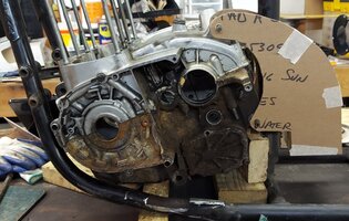
Your input is always valued and especially in this instance as I know you have put in some time studying this very idea. I am somewhat concerned about that issue as well. I can get real vertical on the clutch side of the mounting jole but the sprocket side hole has an engine bolt right below it that I believe will limit the angle that can be achieved. There is the possiblity of creating a solid eye to bolt down on both ends after determining the best preload on the front and rear mounts. My 3rd iteration (the previous) eliminated that issue but it is to chunky (could certainly be made more svelte with the ever classic speed holes or some such styling modifications/variation) and does not allow tor loading the mounts. Perhaps a series of selectable bolt holes would solve that issue.
Here is a pic of the 3rd iteration.
You absolutely may.
Your input is always valued and especially in this instance as I know you have put in some time studying this very idea. I am somewhat concerned about that issue as well. I can get real vertical on the clutch side of the mounting jole but the sprocket side hole has an engine bolt right below it that I believe will limit the angle that can be achieved. There is the possiblity of creating a solid eye to bolt down on both ends after determining the best preload on the front and rear mounts. My 3rd iteration (the previous) eliminated that issue but it is to chunky (could certainly be made more svelte with the ever classic speed holes or some such styling modifications/variation) and does not allow tor loading the mounts. Perhaps a series of selectable bolt holes would solve that issue.
Here is a pic of the 3rd iteration.
Attachments
Wow..I misread or misunderstood what I was reading Jim. I need the dogbone to be LESS vertical. Hmmm. My thoughts were that horizontally it would allow the most flex. I may attempt to look at it from that viewpoint and see what a new iteration brings to light before clearing everything and continuing the stripping. I appreciate the insight.
Thanks.
Thanks.
You need the dogbone(s) to do two things....Wow..I misread or misunderstood what I was reading Jim. I need the dogbone to be LESS vertical. Hmmm. My thoughts were that horizontally it would allow the most flex. I may attempt to look at it from that viewpoint and see what a new iteration brings to light before clearing everything and continuing the stripping. I appreciate the insight.
Thanks.
1. Eliminate, as much as possible, the transfer of vibrations to the frames.
Since the (majority of) vibrations are vertical in moment, mounting the dogbones vertically would be a direct transfer.... ie bad. Mounted horizontally means the vibes would just cause the balls to rotate... with no transfer of vertical vibes. Anywhere in between vertical and horizontal will have varying amounts of transfer.
2. Hold the engine laterally (fore and aft). Under power, the pull on the chain is gonna pull the engine aft toward the rear sprocket (this is why Norton made the engine and swingarm a solid unit, to prevent that pull). A horizontal dogbone will hold the engine rigidly against this fore and aft motion while not transferring vibrations. It'll achieve the same as Norton's engine/swingarm unit.
Let me add the caveat that most of the vibes are vertical in nature. There's also a horizontal component to them... less than the vertical, but there none the less. Using dogbones will not eliminate the horizontal component. In other words, it ain't gonna be as effective as Norton's isolastic's. Better, but....
Actually that's a correct statement, in that the dogbones will allow the most flex vertically if they are horizontal. I think you're missing a key part though.... you'll need rubber isolators to hold the vertical.... the engine moves up and down and is restrained by the rubbers... the dogbones are just there to prevent fore and aft movement. It'll take both to get the job done. Neither will work by itself.My thoughts were that horizontally it would allow the most flex.
Yes. Great explanation which gives me a clearer picture of the forces. Absolutely correct.
I already have a couple of ideas to try and image with a new template or two.
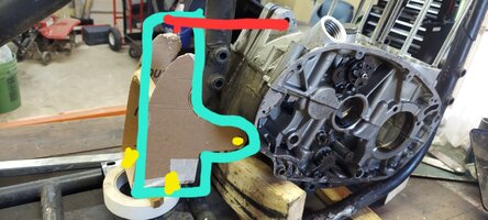
Do you think 2 sets of dog bones would be required or is there potential in pursuing a solid mount to the engine's lower rear mounting holes and a mounting point on the bottom of the "motor mount box" and then utilizing a set of dog bones perpendicular to the engines top rear mounting holes. See this overemphasized drawing on the pic attached.
I am curious on your ideas regarding how/ what the frame side of your dogbones attach...
I already have a couple of ideas to try and image with a new template or two.
Do you think 2 sets of dog bones would be required or is there potential in pursuing a solid mount to the engine's lower rear mounting holes and a mounting point on the bottom of the "motor mount box" and then utilizing a set of dog bones perpendicular to the engines top rear mounting holes. See this overemphasized drawing on the pic attached.
I am curious on your ideas regarding how/ what the frame side of your dogbones attach...
Attachments
I'm thinking a single dogbone will do the job. It'll need to be mounted as close to the front sprocket as you can get. Looked at in absolutes... welding a dogbone directly to the frame and sprocket would do the best job of holding the engine fore and aft. So, the closer as can get to that, the better. Think hard mounting the "motor mount box" to the engine, then soft mounting the "box" to the frame with the rubber(s) and dogbone(s).
The reason I say a single will be sufficient is the front mount will prevent any lateral "rocking" from an offset dogbone. That (all) make sense?
The reason I say a single will be sufficient is the front mount will prevent any lateral "rocking" from an offset dogbone. That (all) make sense?
Yes indeed it does.
Very interesting and I will be doing some deep contemplating on those ideas.
Very appreciative of your input.
I'm going to let my mind wander in that pool of knowledge for a bit. I have things to do while it marinates. I am more confident than ever on finding a path to the goal.
Very interesting and I will be doing some deep contemplating on those ideas.
Very appreciative of your input.
I'm going to let my mind wander in that pool of knowledge for a bit. I have things to do while it marinates. I am more confident than ever on finding a path to the goal.