I recently purchased a PMA from Hughshandbuilt for my 1980 xs650. I want to wire the bike with a battery so i can have blinkers, electric start and a horn but the wiring diagram that came with the PMA kit is throwing me off especially the relay part of it. In the diagram the orange wire goes to the positive side of the coil. The black wire is split with an o ring terminal which i assume gets grounded and then connected to the negative side of the coil. But my kit has a solid white wire with bullet connector and in the diagram there’s a red/white that goes to the positive side of the key switch. I contacted huge and he said 85 goes to the positive key switch but 85 on my relay has a black wire coming from it. The colors from the relay from the kit don t match the colors from the wiring diagram he uses. Can anyone help me please. Also I dont want to run a kill switch. I want the coil to energized from the fuse box which is turn on by my key switch. Some one help me please so i can finish this bike. Also if anyone has a wiring diagram with no kill switch and 4 blade fuse box with only a key please send it to me. Thanks in advance
-
Enjoy XS650.com? Consider making a donation to help support the site.
XS650.com receives a small share of sales from some links on this page, but direct donations have a much greater impact on keeping this site going.
You are using an out of date browser. It may not display this or other websites correctly.
You should upgrade or use an alternative browser.
You should upgrade or use an alternative browser.
Hugh hand built PMA relay confusion
- Thread starter Dxs650
- Start date
IIRC, Hugh includes that relay to work-off the OEM kill switch (that is normally wired in series on coil (+) to make it ground(kill) his ignition. If ya can post a good pic of his suggested wiring, perhaps we can devise a work-around that suits your needs.
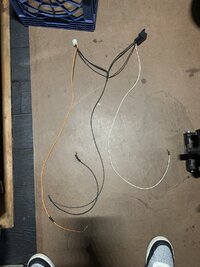
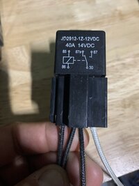
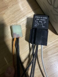
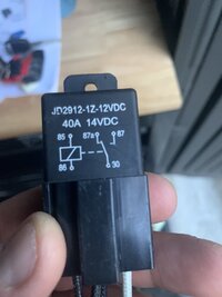
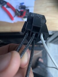
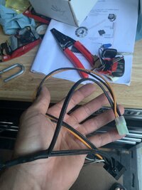
Here’s the relay. The wire colors on the relay dont match the colors on wiring diagram …. Help.IIRC, Hugh includes that relay to work-off the OEM kill switch (that is normally wired in series on coil (+) to make it ground(kill) his ignition. If ya can post a good pic of his suggested wiring, perhaps we can devise a work-around that suits your needs.
Attachments
The inherent design of the CDI is that it needs no external power source for the ignition. So, it doesn't need battery power to the coil; it powers the coil via its own stator windings you need a kill switch to ground the bl/white wire to the igniter box so you can turn-off the ignition. As the OEM kill switch operates a positive lead, Hugh supplied a relay to have it switch a ground wire. If you use a grounding kill switch, you don't need the relay.I want the coil to energized from the fuse box which is turn on by my key switch.
Do you just have his PMA or the full boat CDI charge and ignition system?
From Vape but how they are wired.

I have the kit with ignition and PMA. So you’re saying if i wire up the bike with a kill switch the i don’t need to use this whole relay ??? Hugh said to me if im using a battery then i need the relay. I’d personally rather not use the relay. So i would need my key switch, kill switch and starter button basically right ?? Which diagram would you recommend i use ??Do you just have his PMA or the full boat CDI charge and ignition system?
This wiring diagram does not match what i actually received. The colors on the wires are all different and that’s what’s throwing me off
This wiring diagram does not match what i actually received. The colors on the wires are all different and that’s what’s throwing me off
That's why I asked for a pic of the diagram Hugh supplied with your kit - I wouldn't vary from the wiring Hugh suggested without knowing the system as designed
That looks like a generic relay pigtail. One pair runs the relay the other three blacks the switched contacts
you seem to know your stuff. By any chance do you have a diagram i can use to get this bike running . Hughs diagram and what i bought from him doesn’t match colors. Thats why im getting lost here. On his diagram it shows a white/red to positive key switch but there is no white/red on the relay i haveThat's why I asked for a pic of the diagram Hugh supplied with your kit - I wouldn't vary from the wiring Hugh suggested without knowing the system as design
The (I call it) Red/w/White tracer stripe comes from the OEM kill switch and carries switched positive from the ignition fuse. Hugh specifies that it goes to terminal #85 on the generic relay (that then switches a ground circuit from relay terminal #30 to the kill wire from the Igniter connected to relay terminal 87A on the relay and kills the ignition when the OEM kill switch is turned to OFF
This should help you visualize it better.

Attachments
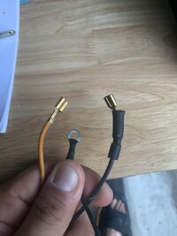
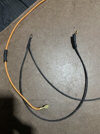
Since that's power, it's possible it's spliced to somewhere else to provide power... who knows.The black wires coming out of 85 are spliced.
Instead of trying to solve this puzzle in bits and pieces, perhaps you can lay all your cards on the table at once? Multiple pics of every component you got with your kit and all the associated wiring?
Did Hughes provide you with a diagram or instructions? Put those up here maybe?