Not really a problem. If someone is converting a rotor chances are they are using a aftermarket pickup.
-
Enjoy XS650.com? Consider making a donation to help support the site.
XS650.com receives a small share of sales from some links on this page, but direct donations have a much greater impact on keeping this site going.
You are using an out of date browser. It may not display this or other websites correctly.
You should upgrade or use an alternative browser.
You should upgrade or use an alternative browser.
TCI Replacement 2020 It Works
- Thread starter Team Junk
- Start date
When I had the old SH I glued a 6mm OD x 0.5mm Neodymium over the top of the old magnet. The new magnet self-centered due to the attraction with the other magnet. I never observed any negative effects. Maybe this was because the magnet was only 0.5mm thick so possibly weaker compared to what other are using?? This is also how I know there is at least 0.5mm clearance under there.
Had 5 hours of driving yesterday, plenty of time to contemplate my fate. When I started this thread I figured it might get up to a couple of pages. Now that it's pushing 600 messages I'm thinking that this thread should be renamed "Gonzo Development" and creating a new thread with the destructions and parts lists etc.
What do y'all think ?
What do y'all think ?
Hey Skull this might be a good pickup alternative for you. Probably a standard Bosch style relay.
I have done a little science project this afternoon. I broke up a small relay to get the coil then glued it to a scrap of metal to mount in the lathe tool post.:

Had 5 hours of driving yesterday, plenty of time to contemplate my fate. When I started this thread I figured it might get up to a couple of pages. Now that it's pushing 600 messages I'm thinking that this thread should be renamed "Gonzo Development" and creating a new thread with the destructions and parts lists etc.
What do y'all think ?
YES - the discussion is fascinating - I have learned a lot - BUT - so many things have been discussed, tried, tested, dissected and discarded that I doubt anyone but TJ, Jim, TooMany and Paul Sutton could figure out what the final, best configuration is - with confidence. This has all been a necessary part of the process, but for us mere mortals, it is challenging to follow.
Sooooo....may I suggest that a definitive "How-To" thread with clear, concise lists of parts, instructions and photos be compiled (and vetted by the knowledgeable people) and then frozen so that a person who wishes to make this valuable upgrade to their bike can do so.
Pete
Yep hard for me too.
Back on page 3.....

....and photographs with circles and arrows and a paragraph on the back-a each one explainin' what each one was....
(see attached - just about 5:06)
(see attached - just about 5:06)
Last edited:
Classic case of blind justice.
Ok. I have pdfs of everything. Let me double check that they have the latest updates on polarities etc. and I will post them here for everybody to check.
....and photographs with circles and arrows and a paragraph on the back-a each one explainin' what each one was....
Funny story about Arlo
When my youngest son was about to go into 1st grade his mother called me one evening and told me to come and pickup "my son". I asked what was up and that I couldn't come pick him up because I was at work covering the Kerrville Folk Festival.
She was mad because all day he was bugging her to let him go see some guy named Arlo who she had no idea who he was.
I told her if she would meet me at the front gate I would get him in. From the time he was little I would sing him the motorcycle song to put him to sleep. His mother still has no idea who Arlo Guthrie is but my son sure does.
Text information is very helpful.
Diagrams and pictures with circles and arrows are an excellent supplements.
But your instructional videos are simply the best, Jim !
Last edited:
Here are the two pdfs that explain the Gonzo process. My plan is to develop then on this thread and as things progress on how to do it I will update them on a thread dedicated to just the directions on how to do it.That post will have a link to here for further info,help, etc
Alright guys. Discuss
Alright guys. Discuss
Attachments
Meanwhile back at the ranch
Thinking about the stock magnet vs neo magnet vs relucter (metal lump on the flywheel)
We know stock pickup and stock magnet work (several running )
On my test stand neo magnet with a relucter style pickup work fine
A relucter and the Gonzo should work fine That's the way they came on the GN250
So other than the startup anomaly ( which from now on while be refereed to as "SA") things are looking pretty good.
My next phase is getting gonzo to work on a PMA
Last edited:
I think Jim's idea of placing the pickup in the center of the stator window has merit. Would defiantly give flexibility on pickup type and mounting.
Paul's idea of using a relay for a pickup also needs to be investigated.
Paul's idea of using a relay for a pickup also needs to be investigated.
This info needs to be in one place so here it is.
Bosch ?? relay voltage specs
Quick question for Paul. Is the piece of metal your using for a mount part of the relay or is that epoxy I see ?
Each rpm is 4 pulses. The coil has a resistance of 335 Ohm and boy is it a cute one. I set the gap between the coil's non-magnetic core and the magnets for approximately 1mm based on me knowing the XS has at least a 0.5mm clearance at the rotor. All voltage and current readings were done on the AC setting. Voltage reading were made with a 4.7kOhm load across the coil and Current reading were made with a 4.7kOhm load in series. I also measured currents without a 4.7k resistor in place i.e. the meter was the load and I call this a zero load current.So here goes:
330 rpm (1320 pulses per minute)
0.2mA
0.97V
Zero Load 4.3mA
1500 rpm (6000 pulses per minute)
1.0mA
4.7V
Zero Load 17.5mA
2400 rpm (9600 pulses per minute)
1.4mA
6.8V
Zero Load 23.6mA
As mentioned above by Team Junk in Entry 544 we do not want the input signal to swamp the Gonzo conditioning circuitry. To illustrate this point I collected some extra data from my latherometer. I used a silicon diode and 1nF ceramic capacitor in series as the load to improve my voltage readings using DC mode and the probes across the capacitor:
RPM (Voltage)
800 (0.9V)
1320 (1.6V)
2200 (2.8V)
6000 (9.5V)
Last edited:
Notice how with the ammeter directly across the coil (almost a dead short) the maximum current flow is 23 ma at almost 0V . 16x current flow over a 4.7K load
2400 rpm (9600 pulses per minute)
Zero Load 23.6mA This is not zero load. The ammeter has a extremely low resistance resistor that the vom measures the voltage across. It is a virtual short across the meter probes.
2400 rpm (9600 pulses per minute)
Zero Load 23.6mA This is not zero load. The ammeter has a extremely low resistance resistor that the vom measures the voltage across. It is a virtual short across the meter probes.
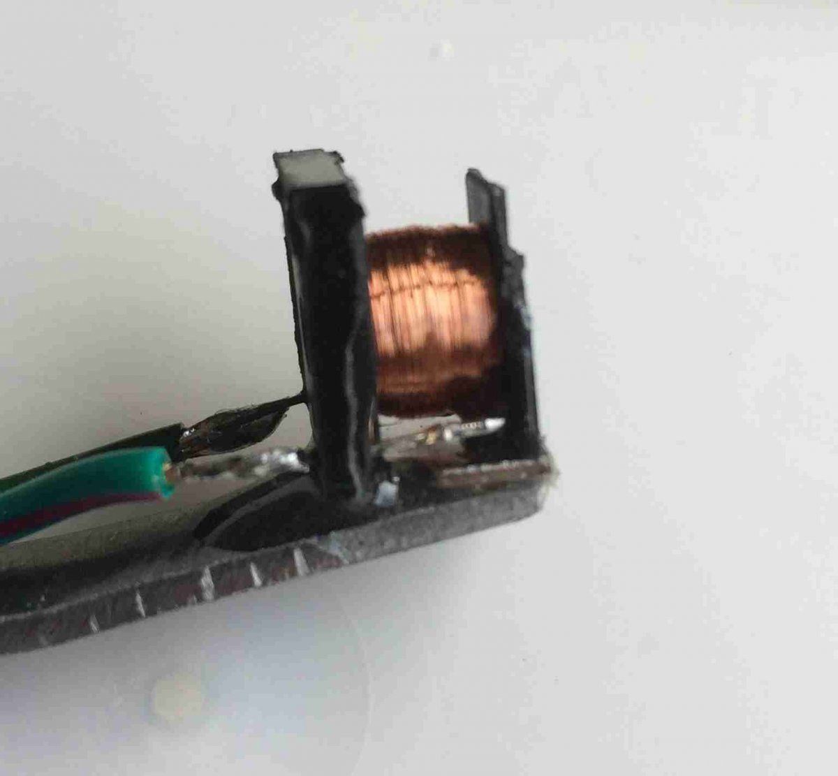
I know I promised but boredom overcame me. The coil I am using comes from a 5pin 12V PCB mini relay:

Bought this for something but never used it. I cracked the cover off and glued it to a piece of steel to mount it on my lathe. The coil resistance is approximately 235 Ohms.
In response to gggGary's question about replacing the magnet with a steel slug I had a go on the Latherometer using the relay coil. The result was no signal observed as expected. The result may differ if a magnetized coil is used but I do not see how this will cause a flux change in the coil. By adding a small magnet to the other end of the coil's core we create a reluctor and do get output signals. Adding another magnet roughly doubled the signal and reducing the gap between the coil core and the steel slug further increased the signal strength. But is it enough to trigger the Gonzo? This all depends on the GONZO's minimum signal specification. Does anyone know what the GONZO's minimum signal level is? Maybe I need to buy a GONZO?
Result sets:
Set 1: Magnet Strength
Pulses per minute = 1500, Gap = 1mm, Signal = 130mV (1 Magnet Fitted)
Pulses per minute = 1500, Gap = 1mm, Signal = 250mV (2 Magnets Fitted)
Set 2: Gap Variation
Pulses per minute = 3000, Gap = 0.5mm, Signal = 380mV (2 Magnets Fitted)
Pulses per minute = 3000, Gap = 0.25mm, Signal = 750mV (2 Magnets Fitted)
Conclusion: A simple DIY type reluctor approach is feasible but may require pre-amp conditioning. What is the advantage of a reluctor approach compared to the use of the TCI pickup coil? Perhaps just another flavor?
Conclusion: A simple DIY type reluctor approach is feasible but may require pre-amp conditioning. What is the advantage of a reluctor approach compared to the use of the TCI pickup coil? Perhaps just another flavor?
It makes the system more universal. The PMA ignition will utilize a relucter and matching pickup.
In response to gggGary's question about replacing the magnet with a steel slug I had a go on the Latherometer using the relay coil. The result was no signal observed as expected. The result may differ if a magnetized coil is used
The good news here is that the steel screws in the stator will not interfere with the magnet signal