Cam Chain Tensioner Adjustment-Video

You adjust the tension so the plunger just comes flush with the end of the adjuster. If it don't come out flush then it's loose, if it comes out past flush then it's tight.
This applies to most engines. Sometimes if parts have been swapped around you may need to alter these settings.
Some combinations of plunger and adjuster the plunger may come out way to far, other it won't come flush no matter how tight.
I have pics that show one from a 75, the other an 82. You can see the differences in the plungers and adjusters. In the other pic it shows how much the plunger sticks out on each year when assembled with out the spring.
If you pull yours out and put it together with out the spring, it should look about like the ones in the pic.
Is so then the stock adjustment is right. If not adjust accordingly or get the right parts.
Leo
 

Attachments

  • Cam chain tensioners 001 (575x492).jpg
    Cam chain tensioners 001 (575x492).jpg
    292.5 KB · Views: 328
  • Cam chain tensioners 002 (474x575).jpg
    Cam chain tensioners 002 (474x575).jpg
    286 KB · Views: 354
i just recently rebiult my engine, and (new chain) i did what the video said,but i noticed that when i crank my engine over with the kick the plunger isn't moving! is that a good or bad sighn its flush with the outside but no moving 1mm?
 
mrkelvinator, If the plunger with the washer doesn't come out quite flush when assembled with out the spring, it will work fine. Just remamber how much below the adjuster it sets and adjust so it moves in/out about 2 mm while idleing.
speez, if it's not moving around 1-2 mm then it's a bit tight. It needs to move some because the srrockets are not exactly round, the places they mount on the cam and crank are not exactly centered, all the links in the chain are not exactly the same length.
All these tiny differences make the chain tight in some spots and loose in others. The tensioner has a spring that keeps the chain tension the same in the tight spots as the loose spots.
The spring pushes the plunger in on the loose spots, and moves back out on the tight spots. With no movement the chain is trying to stretch over the tight spots.
Not a good thing. This shortens chain life as well as extra strain on the cam and crank bearings.
One more thing, the washer was different on different years, Some used a thin copper washer, some a thicker steel and rubber washer. Check on a site like boats.net at the parts fiches to get the right one for your tensioner.
As the engine turns the plunger gets hit against the adjuster, making noise. The washer quiets this noise.
I'll include a pic that shows the different years of tensioners. It will help you determine just what year your tensioner is. All the 6 bolt tensioners can be swapped out year to year.
Leo
 

Attachments

  • TensionerID.jpg
    TensionerID.jpg
    64.1 KB · Views: 427
littlebill,

Adam here new to the xs world, i just received a 81 love the site. Your videos are great thanks for the effort you put forward to produce them there great. One question i did not notice my pin moving at all not sure if that is a problem, any way i set it to flush. On to the valves thanks again
 
With the bike idling it should move in/out about 1-2 mm. If not you have it too tight.
I set it with the bike warmed up a bit, not so warm you burn your hands but warm, At idle adjust so you see the plunger moving a bit. It should come out flush with the end of the adjuster.
If you can't get it flush, just set it to move the 1-2 mm. Any less and it's to tight.
Leo
 
I've made a little video to show how to adjust the cam chain tensioner. It is pretty straight forward to begin with, but video tutorials, which I like better, help compliment written instructions.
Please note that this should be done with a warmed engine.

Thanks for originally posting your videos Little Bill, but it seems it(they) has been made private and we(new guys who need this kinda stuff) can't view them:(.
Visual aids help alot. Feel free to send me your vids via email , Or just come over to my garage and show me how...:wink2: thanks.
 
Thanks Square Circle. I'm going to try this out tonight. I'm a visual learner. I was going to try the written instructions but my bike is in dire straights so some visual proof that I made the adjustment correctly is worth its weight in gold.
 
Yeah same here. I sent littlebill31 a PM about it yesterday. Hopefully it's something he can fix.
 
Another option for uploading videos is Vimeo. They are as good if not better than Youtube. They also have a nicer more modernized design and user interface.
 
Any chance anyone could add me to their video list so I can see the private videos?

My Youtube account name is vdubplate
 
Is that how it works VDub?
If thats the case my youtube account user name is"Giter Dun" .. Or maybe littlebill remade these while in the nude and now their considered biker porn? Hence Private. just kidding Little Bill. :laugh:
 
I don't have a youtube account but I would really like to see the video. I was needing to do this soon. Hope everything get worked out soon.
 
Ok, so since the videos haven't been fixed I decided to read the directions posted with the videos. For god sakes I had to read :)
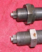
. So I had a few questions I was hoping someone could answer. So for the part about the Cam Chain Guide adjustment the directions say to look for a line. I couldn't for the life of me find a distinguished line. I took pics of what I thought might be the visual indicator on my bike 81, by the way.


img0680u.jpg


img0679x.jpg


Ok, so I moved onto the second part about the valves. Now the directions say not to adjust all 4 at the same time that each side had to be top dead center. Now How do I know when each side is top dead center? Is it as easy as making a guess when you see the piston on either side or are there marking on that brown wheel mentioned in the Cam Chain section?
 
I have not read the directions of which you speak, but I do know how to adjust the cam chain. You can set the engine to TDC if you want but I remove the adjuster cap nut and watch the plunger move as I turn the engine watching for when it moves outward the most. There will be a spot that the plunger jumps out a lot. This is when the valves go over center, disregaurd this jumping. Watch the plunger on the rest of the time you are turning the engine. When the plunger is out as far as it goes stop turning the engine.
Adjust the adjuster so the end of the plunger is just flush with the end of the adjuster. Lock it down.
Now turn the egine oever watching the plunger. It should move in and out about 1-2 mm. I then start the engine and let it warm up some, once warm check the plunger movement while it idles. The plunger should come out just flush and move in/out 1-2 mm. If so then the adjustment is fine.
In your first pic that round dot is the magnet that triggers the pick ups to fire the igniton and get a spark to jump the gap on the plugs.
Your second pic is the line they are refering to. That is the timing mark. When the line on the rotor lines up with the line on the stator to the right of the T the engine is at TDC. When it is idling and you shoot a timing light at those marks the line on the rotor should line up between the two legs of the U shaped mark.
When setting the valves remove the valve adjustment covers, turn the engine over and watch the valves. As you turn the engine over you will see the exhaust valve open and close, that's the one toward the front of the bike. Then as you are turning the engine the intake will open and close, that's the one toward the rear. Now as you turn the engine you will see the line come around and line up with the TDC line. Stop turning the engine. It may turn over a bit more but that's ok. Now both the vlaves that you were watching should be closed. Wiggle them, do they both wiggle/ If so adjust them both.
Now turn the engine over slowly one revolution to line up the timing matks at TDC again, this puts the valves on the other cylinder closed, Adjust them.
Leo
 
Last edited:
That must be the same mark I have in my picture two. That spot is right where the engine wants to spin past.
 
That must be the same mark I have in my picture two. That spot is right where the engine wants to spin past.

in your second pic.. i guess the scribe mark on rotor needs to be directly over the other scribe? or directly over the "T"? i guess either would be close enough.
I have just adjusted my valves usingthe written instructions.. it helped to hold on to the rotor nut with an open ended wrench when it got close to spinning past the mark.
 
Back
Top