Hydraulic clutch conversion

ippytattoo

Just another grumpy old hack.
Messages
1,200
Reaction score
150
Points
63
Location
La Pine OR, USA
First off let me say thanks to osteoderm & Travis for putting me on this path and helping out with finding a suitable slave cylinder and master cylinder combo.

Here is my experience with a hydraulic clutch conversion:

The parts I am using are as follows,
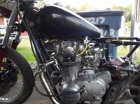
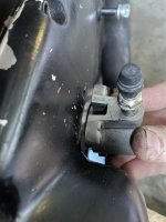
slave cylinder from a 2009 Aprilia RSVR 1000
full

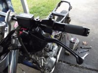
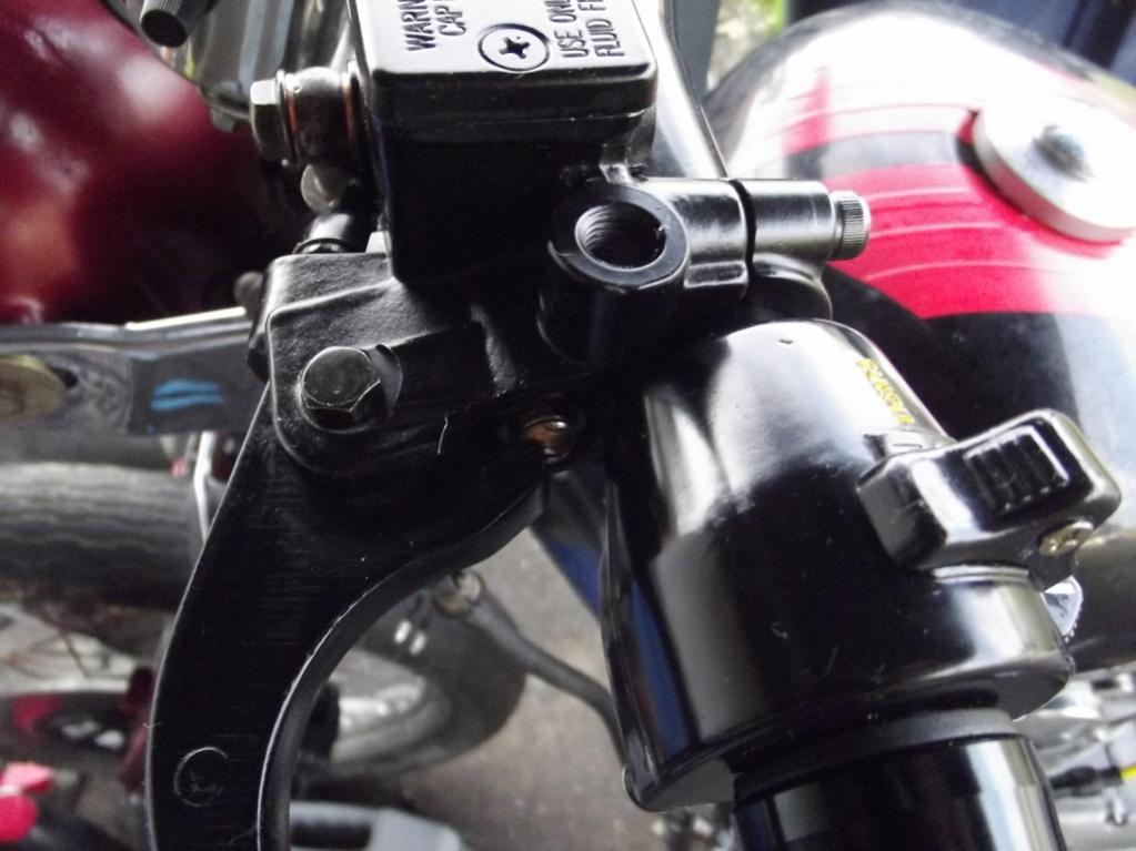
MikesXS clutch master cylinder part#08-0261
full


Modified left hand side cover as described in osteoderms: Good Heart, Bad Intentions: another build thread

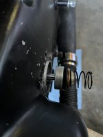
Made a new clutch push rod to replace the original short rod from 5/16 round rod cut to 140mm. When I pull the motor I will be making a single solid rod to replace the 2 rods and 1 of the steel balls.

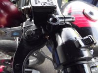
I was first going to use the Magura master cylinder from MikesXS part# 08-0252 but they were not available so I decided to use part# 08-0261 since the bores are nearly identical. When I received the master cylinder and matching brake master cylinder I noticed that the lever was not making contact with the piston when everything was in the resting position (approx. 4mm gap between the 2). Also I wasn't getting the full travel of the piston (lacking about 4mm of travel). So I took the pistons down to a local machine shop and had them drill and tap them for an adjuster screw/spacer
full


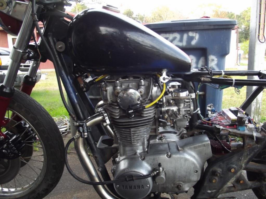
Plumbed up everything with some front brake hoses for testing.
full


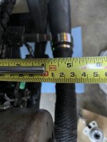
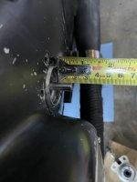
Now for the fun part, measurements(sorry no pics of the meauremens):
With my stock lever and cable at the end of the adjuster screw I was measuring 4mm +/-, 3mm +/- at the pressure plate. So i was having about 1mm of wasted movement in the clutch screw and rods.

With the hydraulic clutch I am getting 3.5mm +/- at the pressure plate. I haven't figured out how to measure at the piston just yet.

The info from Travis's spreadsheet for a 12.9mm master cylinder with a 16mm stroke and a 28mm slave cylinder shows I should be getting around 3.4mm of travel at the piston, so it appears that there is less wasted movement in the hydraulic clutch assembly.

Let me know what you guys think I will add more pics later.
 

Attachments

  • DSCF0438 (1024x768).jpg
    DSCF0438 (1024x768).jpg
    107.5 KB · Views: 494
  • DSCF0429 (1024x768).jpg
    DSCF0429 (1024x768).jpg
    108 KB · Views: 473
  • DSCF0428 (1024x768).jpg
    DSCF0428 (1024x768).jpg
    81 KB · Views: 445
Right on! I'm stoked to see someone else here going for it. As I have so many other projects on my own bike right now, the clutch has been put on the side-burner.

I'm curious to see how the fit of the retainer into the sidecover went; wanted to see if it was as easy for you. I keep thinking that mine was a fluke!

Also, I'm still pondering the best way to interface the new pushrod with the Aprilia piston cup. The inside of the piston cup is radiused; did you match the radius on the end of the new pushrod? I'm toying with the idea of dropping an 8mm ball bearing into the cup, then dimpling the end of the pushrod to fit it (not unlike the stock arrangement, but behind an oil seal).

I measured the pushrod at 8mm. 5/16" is just a tiny hair smaller (7.94mm), but I doubt the crankcase oil seal will mind the difference. I've ordered a 6' length (minimum order) of 8mm precision-ground 17-4PH stainless steel rod. It's more than enough to make a couple test pieces, and possibly 4 more "keepers".

I'm not sure if the pushrods are the same length between model years (same overall length, disregarding one-piece/two-piece differences). If they are, it's no sweat at all for me to make up a batch.

This is awesome!
 
I took a measurement of the hole in the side cover, just a hair under 39mm, and cut the retainer down on a friends small lathe to 38.5mm. I had forgotten to measure the smaller inner hole so it was much the same as yours test fit, file and repeat until it went in fairly easily. I put a radius on the end of the push rod but it was not anything major or very prcise, just something to help keep it in there centered. The one that will really count is going to be the full length rod which will also be hardened at both ends with a dimple for the ball at the clutch end.:D
 
Just took some more accurate measurements of the clutch pressure plate movements with a dial indicator and this is what I got with the setup that I have put together:

I got .122" or approx 3.1mm of actual pressure plate movement. So it seems as though I am well within specs for proper clutch seperation (if not getting a little extra seperation) of the clutch plates.

Hope this helps anyone else who is interested in converting to a hydraulic clutch.

If you have 0.122" of pressure plate movement, that is extremely good. Using the stock mechanical worm gear, the movement is only about 0.053". I modified my worm gear arm so that I now get about 0.073" movement.
 
Last edited:
I had read in one of Travis' post that you wanted between 2-3mm of seperation so I was thrilled to see approx 3.1mm at the pressure plate. And the lever pull is nice and easy and smooth the whole way so I can say that I am truly happy with the investment in this hyd. clutch conversion. Now when I get my new SS braided line it will even look a little better.
 
Great work! Try to find a line with a 90-degree banjo like the stock Aprilia one, should keep the line nice and tight to the sidecover. The slave I ended up with has the stock line attached, but I'm not sure if it will be long enough, depends on your final bar choice.
 
I was looking at maybe a 22* fitting on the end and running it nice and close above the LH cover and then up along the LH downtube. I have put together a mock-up hose and it looks pretty good. I will post pics when I get the motor back in the bike. On a side note I got a really nice crank assembly for a small price so I will have it back in the bike probably in the next week or so, taking my time putting it all back together. It won't be all prettied up on the outside but it will be nice and clean on the inside.
 
Old thread but I'll post my initial feeling here:

I tested my setup today: 28mm Ducati slave with a 12mm master (an Aprilia SR50 scooter left hand brake master). Push rod is made from stock inner rod and shortened Mikes one piece rod. Only could do a short test ride but the ratio seems exellent. Clutch disengages very well, easy to find neutral and good feel when taking off on first gear. Was not able to take it up to high speeds yet.

Pekka

Will you post some pictures of the installation?
 
Here is one pic when I was testing it with the stock brake master. 14mm was too stiff.

The Ducati cylinder is not the prettiest or smallest out there but it fits and does not interefere with the shift lever. Also no machining of the cover was needed. Just aligned it, drilled and tapped the holes ad filed a small flat spot on each hole. Also used copper washers between the cover and the cylinder.

clutch_test.jpg


Pekka
 
IppyT, thanks for all the posts and guidance.

I’ve sourced the parts necessary to convert my clutch. Using the Aprilla slave, the 300mm rod seems too long for my setup. With the piston in place (ball bearing too) the slave and housing will not seat flush with the retainer clip. If the ball bearing is removed, the assembly will sit flush with a little effort.

Does everything need to sit snugly together once assembled - fully compressed, or does there need to be a little free play?
 

Attachments

  • 7B9AEC5C-63D3-40FC-A26A-B35B70C0F378.jpeg
    7B9AEC5C-63D3-40FC-A26A-B35B70C0F378.jpeg
    137.8 KB · Views: 209
  • 0FAB225F-1AEC-40AD-8FB2-C10F1301FA17.jpeg
    0FAB225F-1AEC-40AD-8FB2-C10F1301FA17.jpeg
    117 KB · Views: 215
  • AFA0778A-F31B-44B2-B26F-8A8078DA8E13.jpeg
    AFA0778A-F31B-44B2-B26F-8A8078DA8E13.jpeg
    137.7 KB · Views: 199
  • 1D30443F-E9FF-45B2-9029-86AAE38EB37F.jpeg
    1D30443F-E9FF-45B2-9029-86AAE38EB37F.jpeg
    93.8 KB · Views: 197
IMHO it needs the ball bearing and a bit of freeplay.
 
Finally got to work a bit more on this.

I cut the pushrod down to 290mm and it seats nicely on my ‘81.

These measurements should be about correct — with the ball bearing inside the piston cup, the rod seats 8mm into the cup. I’ve got ~5mm of throw before the piston hits the retainer clip. On the back (spring) side I should have ~3mm of play for when the engine heats up. The piston cup is 33mm deep. With the spring compressed, the piston&spring combo is 25mm deep, which leaves 8mm total play. I decided on 5 in front and 3 in back. We’ll see how it goes.

I thought I picked up a 13mm MC from a ‘14 duc 696. Turns out it is 12mm, and the stroke must be short because I’m only getting ~.05” (1.27mm) at the pressure plate, not the 2mm+ like Travis’s chart indicates. Maybe I need to try a different lever? Will keep whittling away at it and post my mileage.
 
Back
Top