Master Cylinder Rebuilding

Remove the large O-ring from the body. it is a good idea to replace this, but if there is a very good seal, the ring is smooth and pliable, you can reuse it. If the reservoir was leaking between the m/c body and reservoir previous to removal, then the O-ring is suspect and should not be reused.
View attachment 7195
View attachment 7196

Inspect the reservoir for cracks, nicks, and poor condition.
View attachment 7197

You can now remove the brake handle.
View attachment 7198
View attachment 7199
View attachment 7200

BEFORE! you separate the handle from the body note that there is a spring in the m/c body. Once you take the bolt out catch the spring by slowly remove the lever.
View attachment 7202
View attachment 7203
View attachment 7204
Notice the poor condition of the piston. This is caused by the brake lever adjustment screw. Over time a "pocket" or "dimple" will begin, which can cause the improper brake lever pull.
View attachment 7201

There is a small rubber cap that fits over the piston. This is a sealing point. If brake fluid has been leaking out from around the lever and piston this "boot" could be the cause. It looks similar to a top-hat.
Remove this from around the piston. I would not reuse this!, so a pair of needle nose pliers will help it off. You will also notice that there is an internal wire in the bottom lip of the boot. This will corrode over time and will fail!
View attachment 7205
View attachment 7206
What size is the O Ring and where can I get one, I ordered one from McMaster-Carr but it is slightly too big and the reservoir won't push in.
 
I did it, I filed/sanded down the O Ring and sanded down the lip on the reservoir and it is now on and doesn't leak. Now need to find out why the flasher won't work, that's another past.

Thank you everyone for your help
 
Good video with lots of detail, for sure a real help if you've never been in one before.
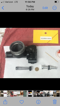
Agreed often the old parts are "fine"
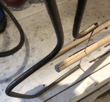
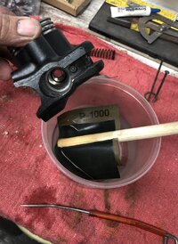
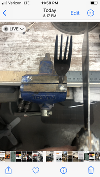
A worthwhile addition to your shop is a double end scribe or pick.

View attachment 117109

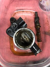
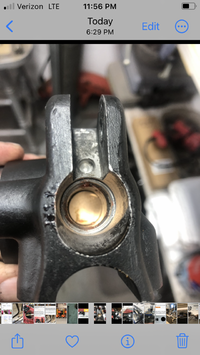
I mention it here cause it's perfect for grubbing out the gunk that has accumulated in the end of the bore over the years. after you get the dust boot out. (you can grab it with a small needle nose and tug and pull it, that rubber is amazingly tough. Use your scribe, work the corner all around the circlip, use the pick to "pop" the eyes loose before you go in with the circlip pliers. If you get the clip loosened and even free enough to spin, the pliers work will go MUCH easier. A long nose micro needle nose will remove the circlip if you have it loosened ahead of time. Doesn't hurt to use a bit of brake fluid on a q-tip to help lube the parts for removal.an air gun also helps get the gunk out, wear glasses!
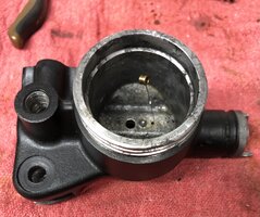
NO steel, brass, or abrasive brushes in that bore, it's soft aluminum! wad papertowel shove it in push out from the other end repeat as needed. You can make a shop hone with a wood dowel. it doesn't have to be snug a bit smaller than the bore is fine. grab your hack saw and cut a long slit in the end of the dowel saw down a couple inches. Now you can slot a bit of FINE (1500, 2000 grit) wet or dry paper in the slot and wrap it around the dowel. this makes a quite serviceable brake hone. Carefully work the bore a bit I prefer to work wet with a bit of water. Don't use a drill or strong force, just light spin clean up of gunk and any light scratches from dragging out the old stuck parts.
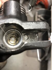
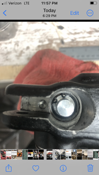
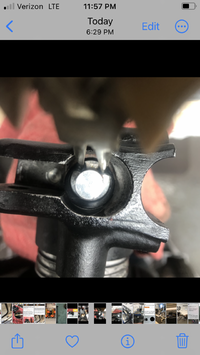
Bob never drill the relief port, it is a VERY fine hole. The factory uses a center drill and just broaches the tip into the bore, they do not use a "fine drill bit" to make the hole. A fine wire will often work to clear the hole. I sharpen a piece of stainless steel safety wire on the bench grinder for fine hole clean out. Some aftermarket MCs have been found with the hole not drilled sloppy tolerences the center drill doesn't QUITE go deep enough. The brake will not relieve pressure without the hole open! 1/16" inch is HUGE, you want a much smaller hole, wheat drill bits can be found. Bob has it right; if you have to clear / drill the hole, go back one more time and hone that bore, so you KNOW no sharp swarf will cut the rubber seals!
Sooooooo thankful for the posts and threads like these. I read and re-read and even though I know that tiny relief port exists and needs to be clearly opened I almost had myself convinced it didn’t it was so plugged.Got it cleared now.
 

Attachments

  • IMG_6437.jpeg
    IMG_6437.jpeg
    280.9 KB · Views: 12
  • IMG_6457.jpeg
    IMG_6457.jpeg
    319.7 KB · Views: 11
  • IMG_6465.jpeg
    IMG_6465.jpeg
    197.3 KB · Views: 13
Sooooooo thankful for the posts and threads like these. I read and re-read and even though I know that tiny relief port exists and needs to be clearly opened I almost had myself convinced it didn’t it was so plugged.Got it cleared now.
Another wise tip found here for cleaning the bore.1/2 “dowel,1000’ w/d paper.Used on one just now.Works quite well.
 

Attachments

  • IMG_6471.jpeg
    IMG_6471.jpeg
    245 KB · Views: 5
  • IMG_6472.jpeg
    IMG_6472.jpeg
    355.3 KB · Views: 5
Sooooooo thankful for the posts and threads like these. I read and re-read and even though I know that tiny relief port exists and needs to be clearly opened I almost had myself convinced it didn’t it was so plugged.Got it cleared now.

Great pics👍
 
The hole in the small round very thin steel attachment provided to attach the rubber puck nipple easily to the spring in this particular kit seems unnecessarily to small IMO.Set a spare original master cylinder spring in a trusty old,easily bent cafeteria fork into a small vise as a starting guide.Removed that spring.Set the new spring in the fork at an angle and lightly squeezed the tines.Enlarged the hole to 5/32 by drilling.Lubed the nipple on the rubber puck with starting fluid.Applied firm flat pressure quickly against the puck with an old strong clean painters putty knife.Although some resistance,it went in and I believe will work fine.Set the copper disc on puck then the plunger on that.I’m following GLJ and others disk placement.I agree that this is about the only position that seems to look correct.I’ll know very soon.
 

Attachments

  • IMG_6518.png
    IMG_6518.png
    1.5 MB · Views: 7
  • IMG_6517.png
    IMG_6517.png
    2 MB · Views: 7
  • IMG_6516.png
    IMG_6516.png
    1.8 MB · Views: 7
  • IMG_6515.png
    IMG_6515.png
    2.3 MB · Views: 6
  • IMG_6514.png
    IMG_6514.png
    1.5 MB · Views: 7
  • IMG_6520.png
    IMG_6520.png
    1.5 MB · Views: 6
The hole in the small round very thin steel attachment provided to attach the rubber puck nipple easily to the spring in this particular kit seems unnecessarily to small IMO.Set a spare original master cylinder spring in a trusty old,easily bent cafeteria fork into a small vise as a starting guide.Removed that spring.Set the new spring in the fork at an angle and lightly squeezed the tines.Enlarged the hole to 5/32 by drilling.Lubed the nipple on the rubber puck with starting fluid.Applied firm flat pressure quickly against the puck with an old strong clean painters putty knife.Although some resistance,it went in and I believe will work fine.Set the copper disc on puck then the plunger on that.I’m following GLJ and others disk placement.I agree that this is about the only position that seems to look correct.I’ll know very soon.
Curious to see how that kit works for you. Where did you get it?
I've had no luck yet rebuilding early master cylinders with kits.
 
Curious to see how that kit works for you. Where did you get it?
I've had no luck yet rebuilding early master cylinders with kits.
I believe Mikes. I had no luck with it either. I cleaned the original guts and trying that route.
 
Back
Top