Supermax vertical mill renovation

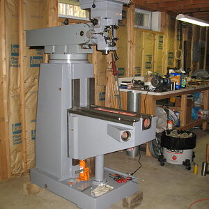
I decided to tackle the quill housing assembly next. I used the H & W assembly videos as a reference and started by installing the quill, quill sleeve (foreshadowing...) and related parts, followed by the power downfeed gears and drive components. This was more time consuming than I expected as there are several gear shafts and bevel gears that need to be installed so everything lines up while also setting the gear backlash. It's a balancing act between smoothness and minimizing backlash. It took a couple of tries, while also finding some parts that needed deburring and massaging to operate smoothly but I was eventually happy with the operation of the gears.


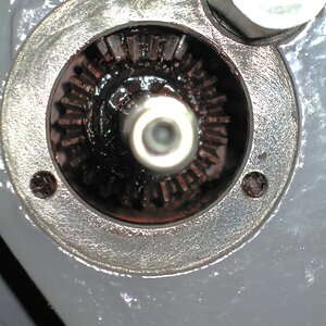
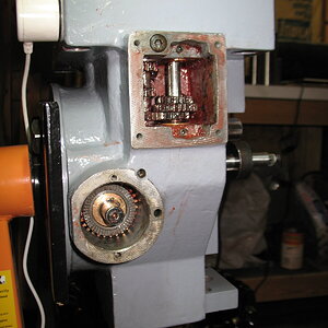
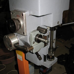
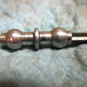
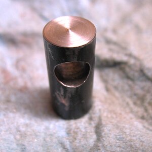
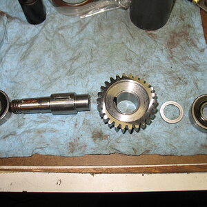
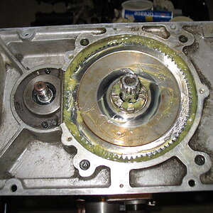
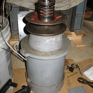
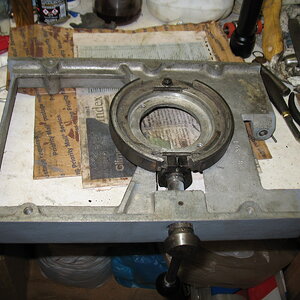
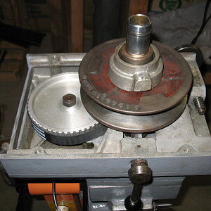
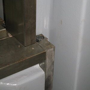
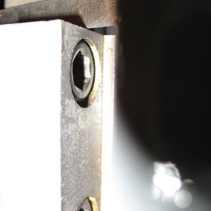
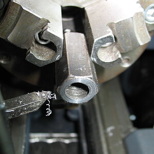
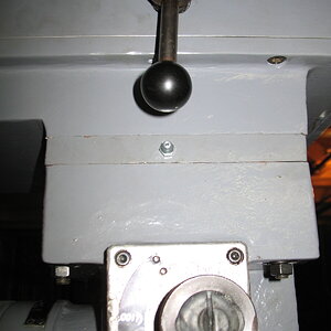
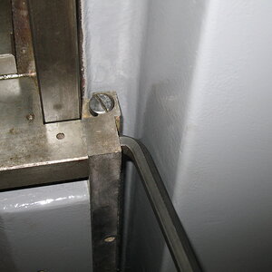
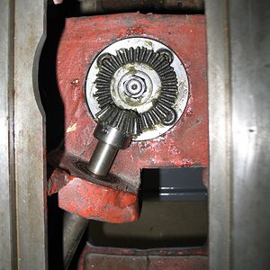
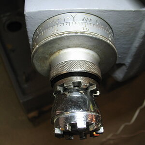
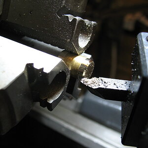
It doesn't look like much; the first picture is the two bevel gears which also has part of the handfeed and dog clutch. The second (upper right) is the gears located above for the three power feed speeds. Below and right of that is part of the power feed clutch which also carries one of the drive gears.

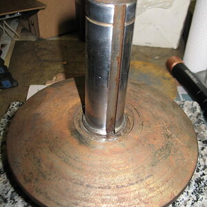
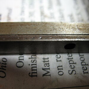
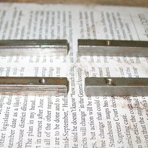
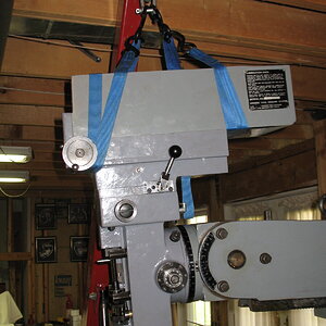
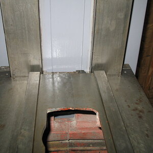
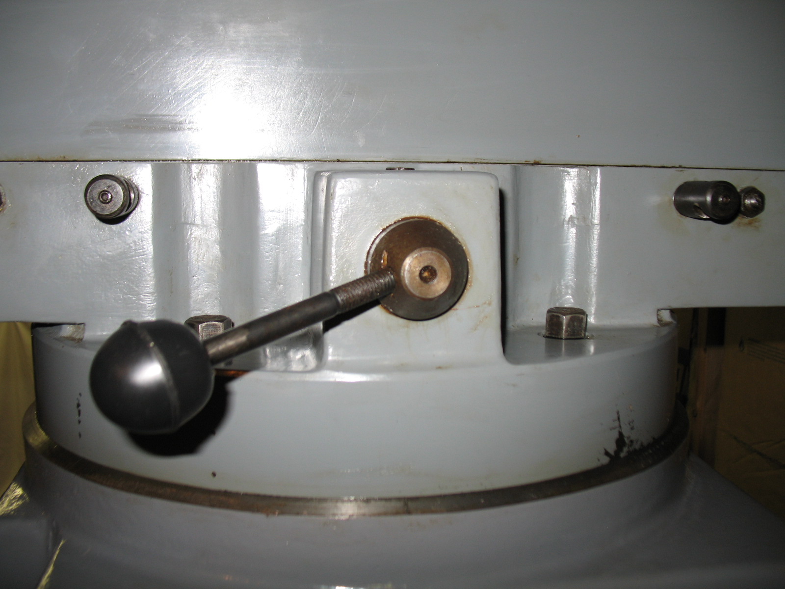
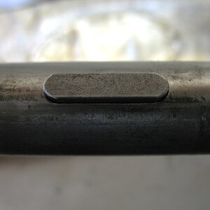
Next came the quill feed shaft, gear and the return spring. This shaft is used for both power feed, hand feed and fine hand feed. After installing and tensioning the spring, the quill would feed down about three inches and then stop, hmmmm. After a little poking around and observation and rewatching the video WITH brain engaged, it seems I installed the quill sleeve backwards and the sleeve was hitting the quill feed gear. Doh!


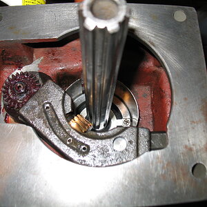
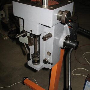
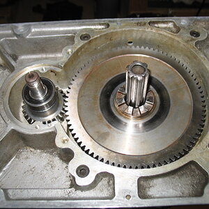
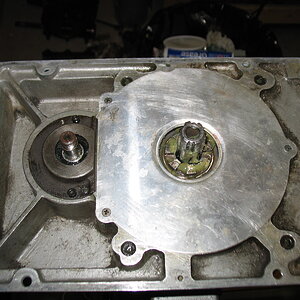
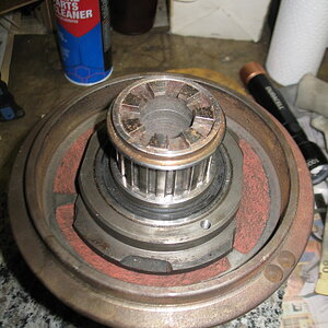
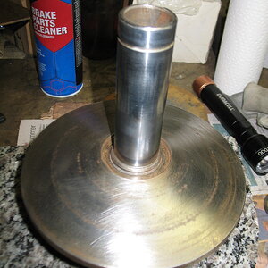
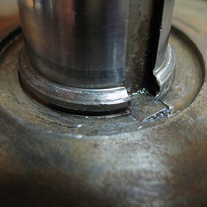
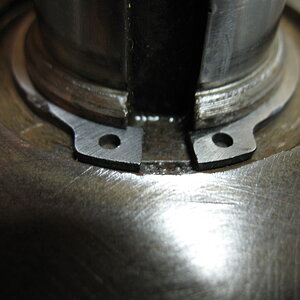
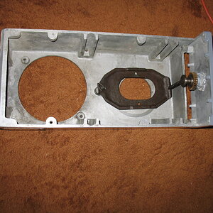
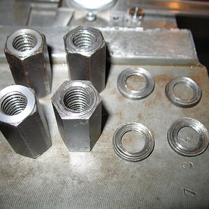
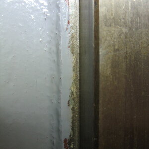
The sleeve is the round sheet metal part around the top of the quill. At the bottom of the picture is the cradle which is used to engage and transfer power for the power downfeed.

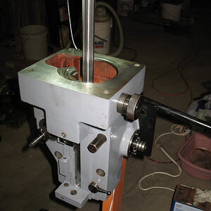
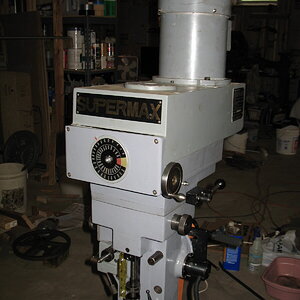
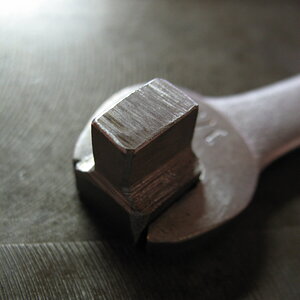
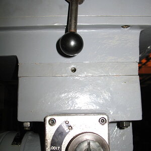
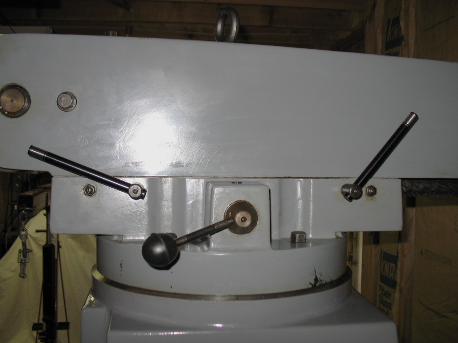
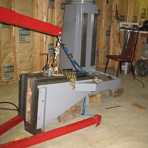
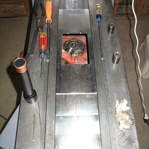
So... I had to remove the cradle, quill feed shaft, clutch and return spring to get the sleeve out! I flipped it around, but it still wasn't working smoothly so I had to massage it using the quill as a form and a dead blow hammer to help it back into shape and deburred all the sharp edges. I reinstalled it and it now works SMOOOTH! I reassembled everything and here we are...


Getting there, one SMALL step at a time.
 
Last edited:
I got the quill housing fully assembled! Kind of a milestone for me.


That's all the "junk" that's in there. Thanks to my friends organizing skills, there were no parts missing.

The worst part was a little gizmo called a reverse feed trip lever (part #183 in the exploded view) that looks like a mini dumbbell, about an inch long.


It passes through the plunger, then the casting and then the quill stop depth screw. I fought with it for a while, tried deburring everything, jiggling everything and no joy. Finally, I turned the housing (engine stands are nice!) on it's side so things stayed lined up better and with much jiggling and spinning, it just BARELY slips in! But it still didn't work smoothly. I tried rotating the plunger 180 degrees and it slipped in slightly better and worked smoothly. (must not be perfectly straight) Success!!

The rest of the assembly went well with no major hiccups.


Now I can move up a layer in the layer cake...the backgear housing comes next.
 
I was a little premature about moving forward. I found another issue that HAD to be taken care of first. (Isn't that always the way...)

There is an auto feed stop mechanism that kicks out the auto feed clutch (under the round cover on the side) so that when power feeding the quill it kicks out the clutch when it reaches the full up or down limit. It's a pretty important item if you don't want to buy a bunch of now hard to find and expensive feed gears. The instructions and videos I've found are good about showing how to set and check the feed trip but only showed a check of the (easier) down feed trip. I wondered about the reverse (up) feed trip, so I tried using it and and...NOTHING! The only way I could get it to work was by adjusting the engagement on the edge of not working and giving the feed trip a hard rap, clearly not right. After a fair amount of noodling and trial and error, it turned out to be two issues. The first was that the little boss on the end of the little dumbbell (reverse feed trip lever) that was keeping the lever from sitting far enough back and would (sometimes) cause the front to catch on the edge of the hole it's in and prevent it from moving.


I filed about 0.015" off the end and now it works smoothly, BUT it still wouldn't trip the clutch.

The second issue was with the feed plunger that the lever fits into. The hole in the cast housing was worn/buggered up from the DPO's (not my friend) and allowed the lever to shift upward when actuating. This forced the plunger to move higher in it's mounting hole until it bottomed (or topped since it's moving upward) in it's mounting hole before actuating the feed trip. A quick spin in the lathe to remove 0.030" off the top and it now works as intended and I can stop having nightmares about shattered feed gears.


NOW I can move on to the backgears.
 
I started assembling the backgears and found a mystery part in with the small gear.


The washer on the right between the gear and bearing is not shown on any of the parts lists or assembly drawings but it was in the bag with all the other small gear parts. I asked my friend if he recalled anything about it but, not surprisingly, after 10 years he didn't recall, but it didn't appear to fit anywhere else. I mocked up the gears and everything lined up well allowing for the thickness of the washer, so I went ahead with using it. The only thing I could figure is that it was added to make pressing the gear on to the shaft easier as it could be pressed on until it bottomed and not fiddling with it's position to line it up with the mating gear, which it did make that easier.


One unexpected and pleasant surprise was that after pressing the bearings into the backgear sleeve, the 'hitch" in the engagement near the bottom of travel had disappeared and it now operated smoothly. The sleeve must have been slightly egg shaped and pressing the bearings in and tightening the assembly made it round again. Whatever the reason, I'll take it as the "hitch" was annoying.

Next came stuffing a tube and a half of Mobilux EP-1 under and around the gears...not my favorite part of the assembly.


Just had to add the sheet metal cover and the next level of the head is...DONE!


Next to assemble is the timing belt, spindle brake and the adjustable pulley.
 
I started working on the adjustable pulleys, driven pulley first. The bearing felt good but a little "dry" so I pumped in some grease using a grease needle so I didn't have to disassemble the pulley half.


Then I flipped it over and cleaned up the pulley face and noticed the snap ring that holds the shaft in looked pretty bad.


Upon removal it was pretty obvious that it didn't fit in the groove and one or more DPO's had tried to force it into the groove. A little research shows this to be an issue with many of the variable speed mills including Bridgeports. The permanent fix is to disassemble the pulley half to remove a spacer under the bearing and surface grind it. I didn't want to do any of that for both cost and time reasons, so I hand lapped 0.005" off the snap ring and now it fits as it should, you can still see some of the remaining "dings" from DPO’s trying to make it fit. All it cost me was a little time and a blister on my right index finger.


I'm sure the press fit is enough to keep the shaft in (must be as it was still in there after 40 years) but it makes me feel better knowing the snapring is now leading a productive life.

When I put the movable half of the pulley on to check the fit it was a relief that the bushings fit the shaft well (REAL BIG pain to replace them and a common issue with variable speed mills) but the key had a lot of slop. After removing it, it was pretty obvious why, the key was now "T" shaped and about 0.020" narrower where it rides up and down in the keyway as the ratio changes.


I figured I better disassemble the motor pulley and check it and it was almost as bad. After taking measurements of all the pieces, the keyways had some slight wear, and the keys were responsible for nearly all of the slop. A little shopping at my favorite hardware store (McMaster) turned up the correct key stock and they even had oversized metric keys in both sizes so that most or all of the keyway wear would be accounted for. All I had to do was cut the key stock to length, drill and tap for the screws that hold the keys in and now the fit of both moveable pulley halves is excellent.


The driven pulley key has two tapped holes as I first tapped it with a #27 drill to give 50% thread thinking that the 1045 steel the keys were made of would be hard to tap to full thread but this proved not to be the case, so I flipped it around and drilled it with the standard #29 tap drill to give full threads.

The variable speed pulleys should now comfortably outlive me and likely it's next owner too and I can continue on with assembling the head.
 
Last edited:
Here's the motor adjustable pulley installed.


Next came the spindle brake. It, like everything else on this machine, took a little massaging to correct all the wear and tear that's accumulated over the years. At some point the brake shoe pivot had come loose and did some minor damage. After getting the pivot installed, the LAST thing I did was put a drop of Locktite on the threads so that doesn't happen again.


When I put the pulley on the brake and gave it an obligatory spin, grind..grind..grind...hmmm.

After about two hours of measuring, deburring, modifying this and that including the shoes (which had lots of wear marks on the top surface, (in hindsight, probably from the loose pivot) I finally found the culprit. The brake cam was located on the shaft with a roll pin AND a set screw (which seemed odd). After trying enough things and spinning the pulley enough times I noticed cast iron dust collecting around the set screw and a TINY shiny spot starting to appear on its top edge. My guess is a DPO had added the set screw for who knows what reason. I removed it as "surplus to requirements" considering the roll pin was probably several times as strong and the problem was sol-ved.

Next came the timing belt and pulley that powers the back gear pinion and the variable speed pulley and it's actuating bearing.


Then the speed adjusting parts in the top cover.


And finally the money shot...


The head is done!! Or at least as done as it can be until it's installed and running to do final adjustments to the speed change mechanism, assuming the motor runs which my friend couldn't guarantee as he never tested it, fingers crossed. Now I just need enough dry weather for the ground to firm up so I can get the base into the basement. Until then there's not much to do so fingers doubly crossed.
 
Thanks Gary, it's been a challenge at times but so far, I'm very pleased with the way this is turning out. I hope 🤞🤞🤞 that I'm past the worst of it. Yes, I just jinxed myself, but I knocked on wood so it's ok. (Actually, I knocked on my head so same thing.)

It's been a great learning experience and I KNOW how everything works now.
 
I've been watching the weather, waiting for any kind of window without rain to allow the ground to dry out enough to move the 1000+ pound base into the basement. This has been the 4th wettest March/April in history for this area so more than one day without rain has been a rarity. I saw that we were going to have a 4-day dry spell and today the ground was FINALLY (and surprisingly) dry enough I was going to give it a try with fingers (and toes) crossed. 7am this morning I moved the trailer up to the driveway and rolled the base out of the garage and behind the trailer.


Next, I lifted the base up and backed the trailer underneath. I had to add about 250 pounds of weights to the front of the trailer to get about 50 pounds of weight on the tung as I could only reach far enough with the hoist to get the base about a foot behind the trailer axle, and I didn't want the trailer tongue trying to pull itself off the ball.


We then drove it down the hill and backed it to the edge of the brick patio near the basement doors, lifted it up and pulled the trailer out from under and lowered the base back down onto the hoist legs and pushed it into position in front of the doors. We then set it down on blocks and positioned the 2x4 runners, channels and pipes under the base and used a prybar to remove the blocks and lower it onto the channels.


Finally, my son and I rolled it into the basement on the pipes. The only tricky bit was positioning the pipes so that we didn't get hung up on the threshold.


All told, it took about three hours total, and the actual moving took about two hours and really couldn't have gone any smoother. The ground was a little soft, so we had to mash the ruts down flat but really not bad at all. Now I can move forward with assembly.


Snug as a bug in a basement. And what do you know, we're supposed to get another half inch of rain this afternoon, then more tomorrow and more still on Friday and Saturday. Sometimes things just go your way...
 
Today I cleaned up the basement and moved stuff around so I could place the base in its final position and have room around it to assemble with the hoist. Then I got the base off the pipes/channels and put it up on blocks so I could use the motorcycle/ATV lift to roll it into position. I had to leave it up on blocks in order to reach in far enough with the hoist and I will have to remove the blocks and drop it to the floor when it's fully assembled.


Then I picked up the turret/ram assembly, greased the mating surfaces, got it into position and lowered it into place.


The only tricky part was balancing the "spider" (The X-shaped piece that clamps the turret to the base from underneath.) inside the base and lining up the turret so the bolts would start in the tapped holes in the spider. There are four cast bosses inside the base that are supposed to hold the spider while it's being bolted up, but it BARELY overlaps them AND the bolts were about 1/8" short of engaging the threads. I put small wooden blocks under the spider to get the bolts to start but it's super easy to knock the spider off and have it clank its way down to the bottom of the base. I was EXTRA-SUPER-SPECIAL careful and got it on the first try. There's that blind hog with an acorn again...


It's starting to look like something...
 
Today's job was installing the head. I decided to remove the motor to make the head less top heavy as I kept having visions of it trying to flip-over during the install. First, I had to put the engine stand up on blocks to get the hoist legs underneath it so the hook would reach the center.


Then I put a couple of straps on it and attached them to the swivel in order to lift it off the stand.


I ran the ram all the way back so I could get the head near it and then, when the head was level with the ram, I could just run it forward as needed to run the four bolts from the ram into the head. As I lifted, I was sweating having enough headroom to reach the ram...


As you can see, it was REALLY close! I had to lift until the boom hit one joist and then move forward until it hit the other joist, all the while hoping I wouldn't run out of room.

Once it was high enough (Hallelujah!!), I had to "nod" the adapter down a little and swivel the turret as the head wasn't quite there and the hoist wouldn't go in any further. I got each of the four bolts in while advancing the ram and wiggling the other bolts while raising and lowering the hoist as needed. Kinda fiddly but not horrendous and I finally got the nuts started and pulled the head the last quarter inch or so into position using the bolts. As it turns out, it was a good thing I removed the motor as there is no way I could have lifted the head into position with it installed.


Eventually, everything was seated and tightened up and I could unpucker various parts of my anatomy...
 
Last edited:
Today was install the knee day. First step was figuring out how to rig it so it would lift nice and level front to back and side to side to make it easy to mate up with the ways on the base. I put a piece of square tubing down inside through the opening in the top and clamped it in place with C-clamps to keep it from shifting. Then I wrapped the chain twice around the tube so the chain would cinch up and not twist while lifting. Last, I put a cam-lock strap from the front of the knee to allow leveling the knee as there was an internal cast rib right at the balance point so it was front heavy. If it hadn't been front heavy, I probably would have shifted the tube so it was so that I could make fine adjustments with the strap for leveling, which worked very well. Having it level made bolting the guide plates, the bolt-on back part of the knee ways, easier to install. (more on that later)


I lifted the knee into position and moved it back towards the base to fit the U-shaped slots in the back of the knee over the base ways.


Next, I started bolting on the guide plates and found my next challenge. There is only one inch from the back of the guide plates to the base.


The bolts would fit if put into the counterbores at an angle and I could screw them in part way by turning them with my fingers, but how to tighten them? Maybe I could have cut-off an Allen wrench to just fit in the gap, but these are M14 bolts with 12mm sockets in the top and I don't have a 12mm Allen wrench. Sooo, it was time for a "field expedient" solution. The only thing I had that was close to the socket size was a piece of 1/2" key stock. I ground it a little over a 1/4" wide and 12mm high with a 4" angle grinder so it just fit into the socket and drives off two of the flats and left the rest of it 1/2" square to turn with an open-end wrench. Not pretty but it worked well enough.


It's not strong enough to tighten them but I could get them snug so I could then insert the gib strips and put a wood block under the knee so I could let the knee down and get the hoist out of the way.


Finally, I ordered a 12mm Allen wrench AND a piece of 12mm 4140 hex stock. I will cut down the Allen wrench so that it just fits in the gap AND cut a piece of the hex stock so I can slip it in and turn it with the closed end of a combination wrench and whichever allows me to tighten the bolts the best will be declared the winner and still undisputed champ.

As gggGary would say, this part was a bit of a "wrastling match"...
 
Last edited:
After a trip to McMaster, today was mostly little projects day.

First was cleaning up the face(s) of the clamp bolts for the quill housing. I had to take about 0.020" off to get them to clean up. I also replaced the corresponding soft steel washers with hardened washers. The washers were so soft and mashed so badly by the bolts that they had to be threaded off the bolts to remove them. As long as I was at it, I also replaced the lock washers on the turret with the same hardened washers. Now they all feel nice and solid.


I also replaced the missing grease zerk for the backgear bearing sleeve. The only place that had the metric fittings in stock and available today was McMaster, my favorite hardware store. (Have I mentioned that before?)


I also made some handles for the ram locking clamps from some 4140 shafting, since it didn't come with any.

full
full


The DPO had cut down the key from 4mm high to 3mm rather than deburr the keyway in the knee elevation crank adapter, so I deburred the keyway and made a new 4mm SQUARE key from a length key stock.


No more sloppy handle.

Next, I took my new 12mm Allen wrench and cut the end off so it would JUST fit into the guide plate bolts without hitting the base. As a side benefit, the wrench end was long enough that I could use the cutoff part with a combination wrench so I didn't have to buy a piece of hex stock, so it wound up being a two-fer. I tried them both and the cutoff wrench was much better for final tightening as the handle was a couple of inches longer than my 12mm combination wrench.


It just barely squeaks in past the base and fully engages the socket in the bolt head. I'm going to make an extension from a piece of black pipe to give the bolts a little more oomph than just the 8" wrench handle can deliver.

The last item on my list for the day was to figure out what was going on with the gibs. When I put them in yesterday. they didn't feel right. They wouldn't seat or adjust well at all and there was no "feel" to how tight they were getting. Now that I had enough tools to effectively work with the guide plate bolts, I decided it was easier to remove the knee to better see what was going on. Turns out there is some paint on the edge of the ways where the side of the gib rides so the gibs didn't slide and were tight in the ways. Tomorrow, I will clean up the offending paint and re-install the knee.


I will also take the opportunity to run a tap through the holes for the gib adjuster screws as they also made it difficult to "feel" how tight the gibs were.
 
Last edited:
Thanks Jim! It will definitely be as good as I know how to make it.

Actually, I did! I recently bought an old Kalamazoo horizontal bandsaw that was made somewhere between 1939 and 1941. It's a 700-pound beast that needs some work. One of the things it needs is a new half nut for the vise. A replacement from Clausing is over $300 so I will buy a generic nut from Roton for $50 (actually makes 2 half nuts) and modify the original nut to take an insert.

https://www.xs650.com/threads/is-it...-mills-and-other-shop-tools.50953/post-833668
 
Today I removed the paint that had been making it difficult to install and adjust the gibs. I also cleaned up the guide plate bolts and taps to make bolt install easier (still not easy). I ended up using all three of the tools I made to install them as each one made some part of the install quicker/easier, and this time I remembered to lube all the way/gib surfaces before starting the installation. Once the knee was back on, I installed the elevating components.


I did find out why the key in the crank adapter had been filed down by the DPO. The sleeve that fits over it and holds the dial parts couldn't fit over the full height key, but it covered the key when installed so the key couldn't be installed after the sleeve. I filed it down the absolute minimum amount to allow the sleeve over. So, the key did need to be filed down but nowhere near as far as the DPO had.

Next I set the sliding guards on top of the knee. This should be a simple plop them in place and done kind of thing but, as usual, each piece needed some tweaking to sit flat and engage properly with its neighbors.


Then I installed the knee locks but had to modify the knee lock plungers (say it ain't so!) as the ends had bulged out from being mashed against the ways hundreds or even thousands of times over the last 40 years. I removed the bulge and chamfered the ends to (hopefully) delay the bul-ges in the future.


Lastly, I did the final adjustment on the gibs and the elevating pedestal and installed the way wipers, all done and everything works very nicely.

 
How you gonna get those wood blocks out from under it? :er:
 
VERY carefully!

Actually, the same way I got it up on them initially, by using a prybar at each corner and a large number of different size wood blocks and drop it a little at a time at each corner until it's down. Not so bad, just a little tedious.
 
The bar I've been using isn't very long (23") and I haven't had to deal with the full weight yet, so I may end up treating myself to a longer bar if using this one proves to be difficult/impossible. We shall see...
 
The bar I've been using isn't very long (23") and I haven't had to deal with the full weight yet, so I may end up treating myself to a longer bar if using this one proves to be difficult/impossible. We shall see...
Got a 5ft (I think :umm: ) pry bar 'round here somewheres. Iffn you could find a place to wedge it, you could rotate the earth backwards. :wink2:
I'd loan it to ya, but you know.... Ohio.
 
Back
Top