oiler hole ??? in Sprocket-Side Case Cover

willis, thank you for the interesting plugged breather pic.

Hmmm, a square-corner 1975 confuses things. Maybe a very early 1975? More reports from 1975 owners would help, as well as VINs, so maybe we can figure out when changes were made. bluesman and willis, would you mind sharing your VINs?
As I shared in a related thread, I have a round-corner 1975 engine with VIN 447-115238. 1975 production started with 447-100101, so I think mine's late 1975.
The parts bike with the rounded corner and hole is 447-127044. I'm not real comfortable giving out the full vin but it is a early model. partial vin is 447-103xxx.
 
Thank you bluesman.
A partial VIN like bluesman provided works just fine if anyone else wants to contribute.
 
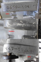
That "365" stamping looks suspicious.

Found a "365" model code for 1973 MX360(A)...
I found that MX360 "365" prefix reference also. I am almost certain that my mystery XS650 engine is not a MX360...
However...
Untitled-3.jpg
You are absolutely right, that 365 VIN stamping is VERY suspicious. It is a completely different font. Compare the 2, the 3, the 4, and the 6 on my mystery engine to stampings on an earlier and a later engine.
There are zero signs that the mystery VIN was tampered with. It was just stamped at a different time or place than a normal 1973 or 1974 decompression engine. It's as if the engine was pulled from the assembly line for some reason before it could be VIN stamped, for testing or something, and then after the testing was over, some engineer in a satellite facility just threw a random VIN onto it using an atypical set of number punches. I don't know, come up with a better explanation.
 
Piledriving thru factory parts manuals reveals:

306-14511-00 - 1972 XS2 left cover
306-14511-04 - 1972 XS2 left cover

306-14511-04 - 1973 TX650 left cover

306-14511-01 - 1974 TX650A left cover
306-14511-04 - 1974 TX650A left cover (superceded by 584-145111-00-00)

306-14511-01 - 1975 XS650B left cover
306-14511-04 - 1975 XS650B left cover(superceded by 584-145111-00-00)

584-14511-00 - 1976 XS650C left cover

584-14511-00 - 1977 XS650D left cover
584-14511-00-00 - 1977 XS650D left cover

584-14511-00 - 1978 XS650E left cover
584-14511-00-00 - 1978 XS650E left cover

584-14511-00-00 - 1979 XS650F left cover
584-14511-00-00 - 1980 XS650G left cover
584-14511-00-00 - 1981 XS650H left cover
584-14511-00-00 - 1983 XS650K left cover

As usual, it's a mess, and this list probably doesn't help.
None of the parts pics show the oiler hole or the rounded corner.
Some of the parts pics show the embossed "1-N-2-3-4-5" shift label, some don't, inconsistently.
I'm sure that there's other parts manuals and bulletins forever lost to time.

The 306 suffixes -00, -01, and -04 may provide clues.

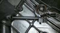
Might could check inside the covers for casting numbers.
WormP01.jpg
 
Dude, thank you, added to the list.
bluesman, I have measured several holes, and they are all in exactly the same position and appear identical, indicating that they were made at the factory.
Skull, yes, it appears to be a mid 1975 change. Now we just need to figure out when the oiler hole and the gear shift number stamping first appeared.
2M, good eye, I had no idea that there are casting numbers on those covers -- they are on a surface that typically gets completely grimed over. So, I looked at some of my covers. Thus far, I have come across two different number variations, but I haven'e had time to figure out what the difference is, if any. But I have also come across a sguare cover with hole, round cover with hole, and round cover without hole, all with the exact same cast number. So, they were doing some cover changes without bothering to change the number on the mould.
 
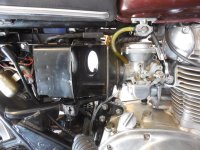
I am working on a catch can to replace my breather set-up, but I have a couple hesitations in moving forward with it..
One is that what I have now is basically the stock configuration, which I generally prefer,
and two is that the oil mist, despite making a bit of a mess on the inside of the case, seems to oil the chain just about right..:)
 
You mentioned having a PCV valve hooked to it. Actually, they don't work in this application. They have a little metal ball or "BB" inside that moves back and forth, opening and closing the valve. Well, it can't move fast enough to match the engine pressure pulses. Basically, it probably just ends up stuck open. What we use here is usually a power brake check valve. That has a rubber flapper inside that apparently can "flap" fast enough for this purpose.
 
You mentioned having a PCV valve hooked to it. Actually, they don't work in this application. They have a little metal ball or "BB" inside that moves back and forth, opening and closing the valve. Well, it can't move fast enough to match the engine pressure pulses. Basically, it probably just ends up stuck open. What we use here is usually a power brake check valve. That has a rubber flapper inside that apparently can "flap" fast enough for this purpose.
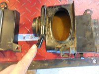
5T, what do you think of using an in-line oil/water separator as a catch-can for the breather line?
That is, a Central Pneumatic separator which is used in the typical air hose ?
Would the inlet hole size be too restrictive?
It would be easy to adapt, and only 6 bucks at HF.

image_14002.jpg


CentralPnuematic.gif

This unit separates oil and water to prevent rust and corrosion from your compressor. The handy oil/water separator works at 90 PSI to prevent condensation from contaminating air tools, keeping your air tools operating at peak performance.
  • Unit can be used with any compressor
  • Gives you top efficiency with any type of air tool
  • Working pressure: 90 PSI
  • Air inlet: 1/4 in. - NPT
 
I never thought of an oil/water separator. I don't know how it would work. I guess all you can do is give it a try.
 
covers.jpg

Adding another cover difference to this thread. Sometime after 1975 a screwdriver slot for prying the clutch adjuster cover was added -- seen in the top cover in the pic. The lower cover is a round corner 1975 with oiler hole and part # 306-14511-0 cast on the back. The upper cover is unknown year after 1975 with round corner, no oil hole, and part # 306-14511-04 cast on the back.
 
More left-side case cover weirdness.
Apparently, Yamaha was making changes to the really early covers so fast and furiously that they didn’t even try to document all of them or assign them different part numbers.

DSC02615.jpg

As has been already noted, the early covers did not have the shift pattern cast in next to the shift shaft hole. Well, the really early covers also didn’t have the “Made in Japan” casting. So, the very first covers had no cast-in labeling at all, then they added “Made in Japan” at some time during 1971 (?), and finally, they added the shift pattern, around 72-73?

s-l1600a.jpg

Obviously, the location of the bottom, rear, mounting bolt hole changed when they added the electric starter. But here is a version where a bung for the new bolt hole location has been added, but it’s not drilled out, and the kick-only bolt hole location is still being used. For me, this cover is an aberration that does not neatly fit into the cover time-line. Maybe these were specially created on an as-needed basis from 72 and later castings to accommodate 70 and 71 owners who needed replacements for covers that they had damaged?

DSC02618.jpg

The location for the clutch adjuster spring’s anchor point went through three changes. This is the final location.

DSC02619.jpg

That location was preceded by this location, used in 1971. Just a subtle re-positioning -- unlike in the previous picture, this anchor point is centered on the reinforcing gusset. Note the un-used bung.

s-l500.jpg

That un-used bung in the previous pic is the original spring anchor point location, used in 1970.
There are several other features of the 70 and 71 covers that make them unique to later covers, but they are minor.

s-l500a.jpg

The back-sides of these covers have part numbers cast into them. The earliest number that I know of is 256-15411, with an additional -1 on a separate line. I am just about certain that this designates part number 256-15411-01. The -1 casting is found on covers with both of the two earliest adjustment spring anchor locations. To reiterate, the very earliest covers have the 256-15411 -1 casting, no shift pattern casting, no “Made in Japan” casting, the “kick-only” bottom, rear, bolt hole location, and no additional, but un-drilled bung that will become the new e-start bottom rear bolt hole location. Covers with this part number stamp can have either of the two earliest spring anchor positions.

DSC02621.jpg

The next cast-in part number that I know of is 306-15411-0 with an additional -2 on a separate line. Undoubtedly, this designates part 306-15411-02. This casting began in 1972, and therefore marks the advent of castings that have a bung for the new, bottom, rear, e-start, mounting bolt hole location (whether or not the new bung was actually drilled out and used). They made lots of changes to this cover without bothering to change the part number on the mold. All of these covers have the “Made in Japan” casting. The earliest still don’t have the shift pattern casting, but this was soon added. These covers come in both square- and round corner iterations, and they come with and without oiler holes.

DSC02620.jpg

The final cast-in part number that I know of is 306-15411-04. These covers are differentiated from all of the earlier covers by having a screwdriver pry-off groove below the clutch adjuster cover. This cover likely came out in mid-1975. 306-15411-04 was superseded by 584-15411-00-00 in the parts manuals, but they never bothered to update the number in the casting molds, i.e. 306-15411-04 is the last number that you will find on a left-side case cover. I have no idea how a 306-15411-04 cover differs from a 584-15411-00-00 cover, if at all.
 
Back
Top