76C wiring question for the wizards...

On my stock wiring harness, in the portion of the harness positioned under the tank I have the following:

Grey x2
Orange x2
Blue/Red and a Blue/White: > Diode
Red/White
Pink, and a Brown: > Horn
Black x1: upper engine mount ground

The above matches the replacement harness from Mikes. I'm also going with a PAMCO e-advance setup, replacing the stock points. The kit included a new coil. Coming off that now single coil, are just 2 wires. A Black/White, and a Blue.
 
The 2 little wires on a single dual output coil are not polarity sensitive. You can hook the Pamco or coil power (R/W) to either one.

The 2 greys (and oranges) should be both ends of the same wire. Test them and see, but that's how the stock harness was. One end should have a single connection, the other a double. These tied your points wires to the condensers then the coils. One points set wire and one condenser wire went in the double end, single end connected to coil.
Thank you 5twins! That is very useful guidance. May I test you one step further? Off the PAMCO and E-advance, are 3 very small wires... Red, Black, Green. What are your thoughts for those!? (I am sure there is a thread to that effect... but since we're on the subject..)
 
Well, I don't have the E-advance (yet, lol), just a plain jane Pamco, but I have studied the install instructions .....

http://www.yamahaxs650.com/Installtion of E-Advancer.htm

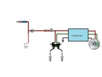
It seems you'll have 2 sets of 3 wires, 3 running in, 3 running out. The "In" wires get connected to the 3 sensor plate wires, the "Out" wires run to ground (black), coil (green), and switched power (red). Pretty simple really. For switched power, I prefer the R/W that powers the coil(s) because you can cut that power with the kill switch. Any other switched power source won't have that feature.

Pete also likes to see the Pamco fused, or actually, the coil, with a 7.5A fuse. Apparently, if the coil shorts out, it can back feed high voltage through the green wire into the Pamco and fry it. Fusing just the Pamco unit won't protect against that.
 
This diagram should help:
Pamco E-Advancer.JPG
 
From Here, http://www.xs650.com/threads/pamco-ignition.46859/

Q,
...........Just got my Pamco yesterday. What kind of connectors do you use on these tiny wires ?
A,.........You can use whatever crimp on connectors you want to. The wire is 22 gauge. The color code for those terminals is red.

Yea i was asking is those Y/G wires in the diagram was on the loom.......

Thanks Skull, nothing Y/G on my loom in the vicinity of the coils...
 
Gordon.......That link is a Pamco install and trouble shooting thread, with wiring diagrams...........have a good look. Bookmark it
 
The safety relay has either two r/w wires or one red and one r/w. Doesn't really matter as it is only feeding power to the start relay, one in one out.
The safety relay has a yellow and black wire, black is always ground. The yellow is from the alternator. When you turn on the key power flows through the safety relay to the starter relay, From the S/R to the start button where when pushed grounds the circuit through the bars and back to frame.
This, if everything is right, starts the engine. Now as the engine starts the alternator starts to create power, some of this power is bled off by the yellow wire to the safety relay. When the voltage on the yellow wire reaches about 4.5 volts the safety relay trips, cutting off the power through the start relay, stopping the starter from running. AS long as the engine is running the alternator will keep the safety relay tripped.
The red wire that supplies power to the safety relay can get it's power straight from the battery. It don't matter where it comes from it only flows when you push the start button. It would be more prudent to have it only get power when the key is on. That way if the blue/white wires shorts out at any time the starter wont run.
Leo
Hello guys , I am restoring a 79 special turning it into a scrambler , it is a 2F model in the serial # , I installed a new wiring harness from MikeXS and so far I have a couple issues that I would appreciate some help to resolve,I also installed a key switch, the starter turns over only if the rectifier is disconnected , I also notice that if the rectifier is connected to its plug , the safety relay clicks on as soon as the battery is connected no matter if the key is on or off and then my starter does not turn other, does replacing the rectifier solve all those issues ?
Thank you for any expertise.
 
Welcome JCM, can't give an answer on the problems your having, i suggest you start you own thread with your problem and give us a detailed account of what has been done to the bike by yourself or supposedly by the PO.

Posing pics can be a big advantage. A lot of bikes are misidentified because the Production Date doesn't necessarily relate to the Model.

Special 2 models Stared in 79 and in 80 the 80G SII visually looks exactly the same as the 79 SII but the Factory changed the ignition to an Electronic one (TCI), and the 79 is points.............80G SII production date starts around September 79 till Aug 80.

Please post at least the first 3 numbers of your ID so we can verify your model

Is the prefix 2F0 ****** or 3G0 ******
 
Back
Top