TimeMachine
SeventyEighte
Peace Skull ! I just have my f**k phone.. If I had a keyboard , well I'd just ramble so many lies, I might even have a "following" 
")
Yes Skull, that wiring would work. The yellow from the stop switch should be rd/white, as that is the colour that most other years used.Is this the way i should be..................Br from ignition switch to stop switch and Y from stop switch could/should be R/W
View attachment 98174

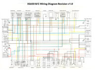
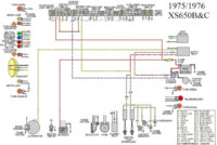
I done a revision of the 75/76 wiring diagram, The one posted in the Tech Menu - Wiring Diagrams thread. I posted an Ignition system part of that diagram in this thread, (based on RG's post), and then i did the revision ready to re-post on here............I didn't post the diagram because there was conflicting information being posted in later posts.
The only real way to reproduce a 76 wiring diagram is to use an original bike's wiring and reproduce that or compare it against a diagram and rebuild as per the bike. Just revising an existing diagram using the input from electrical gurus to fix some mistakes, does not mean that the bikes wiring will be the same.
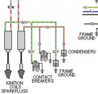
Yuor welcome George............... Question, In the diagram there is the G/Y wire going from the coil to the points/condenser...........Is that a grey wire on the loom you bought or took off the bike