An electronic TDC Finder and ConRod checker

TwoManyXS1Bs

BBQ Hunter
Top Contributor
Messages
14,670
Reaction score
15,295
Points
813
Location
Fredericksburg, Texas
Another little lathe project. I've been wanting to check if the timing mark on my OEM rotor is really showing TDC. 4 things have to be precisely positioned to get an accurate TDC indication.
- The keyway slot in the crank.
- The keyway slot in the rotor.
- The notched mark on the rotor's slipring face.
- The markings on the stator cover
Understandable if there's some inaccuracies there.

Borrowing from the "piston stop" method for finding true TDC. Instead of stopping the piston, this version has a plunger to sense piston position. It's no more electronic than a set of points or brake switch. It just provides a grounding signal when the piston is just slightly below TDC.

I won't bore you with all the lathe operations. They're simple turning routines, but the fit of the plunger within the sparkplug shell must be kept close, like less than 0.001" plunger/bore diametrical difference. Otherwise, the plunger position would be too indeterminate.

A sparkplug's ground lug is cut off, the retaining crimp is machined off the top of the metal shell. Tap on the center electrode with a punch, drive out the porcelain core.
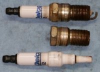
SparkPlugApart.jpg

The shell must be precision bored to get a close sliding fit with the plunger.
This one uses a 3/8" (0.375") plunger.

Here's the finished parts for the tool. Stainless steel plunger, black plastic insulator, brass disc, steel guide rod threaded to #4-40.

TDC-Finder01.jpg
 
Last edited:
Parts for the body group. Sparkplug shell, plastic insulator, brass contactor disc, copper rods.
TDC-Finder02.jpg


The brass disc is notched on the edge at 4 points. Then, the brass disc and plastic insulator are press fitted into the sparkplug shell.
TDC-Finder03.jpg


The unit is chucked up in the lathe, and the brass disc is faced-off, perpendicular and square to the unit.

The 4 copper rods are pressed into the 4 notches. Epoxy is carelessly blobbed around the copper posts, for holding and sealing.
TDC-Finder04.jpg
 
Last edited:
Parts for the plunger group. Plunger, guide rod, spring, contactor nuts.
TDC-Finder05.jpg


The guide rod is press fitted into the hollow plunger. The spring will apply only a few ounces of plunger force.
TDC-Finder07.jpg
 
The engine is set to as close to TDC as possible, by watching for the plunger's guide rod to protrude as much as possible. The contactor nut is run down to just touch the brass disc, then backed off to get a spacing of about 0.013", which is 1/2 turn on the #4-40 threads. The second nut is spun down onto the contactor nut to lock it. Just mild finger forces used here.

The crank is rotated back-and-forth about +/- 15 degrees several times to get the plunger to crush/settle into the grimy surface of the piston dome. The contactor nut is readjusted to reacquire the 0.013" (1/2 turn) clearance.

Now we're ready to find TDC. Turn on the multimeter, and slowly rotate the engine back-and-forth about +/- 15 degrees. Watch the rotor's alignment mark while listening to the multimeter's beeper. The midway point between the beeps is the true TDC. I found mine to be about 2 degrees off.
 
This piston position chart should help to understand the crank angle to piston position.

XS1B-PistonPosition15_smlr.jpg


Presetting the plunger clearance to about 0.013" should get beeps about +/- 7 degrees aside TDC. One degree of crank rotation on our XS650 rotor is about 0.035" at the rotor's edge. +/- 7 degrees would be about +/- 0.245" (6mm) of travel at the beeps. Plenty close enuff to get true TDC...

Edit: Replaced that *huge* chart with a smaller one...
 
Last edited:
Nice work, 2M.

As you know, I took a mechanical approach to developing a piston position measurement tool.

I started with a spark plug non-fouler,

001.JPG


drilled and tapped for 3 set screws, to hold my dial indicator firmly:

nonFouler 004.JPG


nonFouler 006.JPG
 
Last edited:
Dude and TM - All good stuff! I have another idea to throw in. Fit a small connector to the dummy spark plug and take the piston close to TDC. Now connect one side of your homemade PVC carburetor balancing U-Tube and finely adjust the piston location until the fluid level shows TDC. Might work??
 
I found the angle of the spark plug hole to the piston to obtuse to get accurate readings with my plunger type DTI. I might try again with a lever type DTI when I get one.
Dude yes a DTI on RD's is a must.
 
Glad you brought that up, Signal. The sparkplug hole is 30° from horizontal. The piston dome at the plunger contact is about 25°. When you do the trig, it turns out that the plunger travel is close to the piston travel, as long as the plunger can't wiggle sideways. Best to keep the motion at the last 0.040" (1mm) of travel, about +/- 12° of crank motion...
 
Last edited:
...I started with a spark plug non-fouler,...

Dang, THAT's what I should try next.

...Fit a small connector to the dummy spark plug and take the piston close to TDC. Now connect one side of your homemade PVC carburetor balancing U-Tube and finely adjust the piston location until the fluid level shows TDC. Might work??

Paul, could be worth trying. Even with the small piston movement, there's still a significant amount of volume displacement, about 0.11cc per 0.001" (0.025mm) of piston movement. That would show as 5/8" in a 3mm tube...
 
Back
Top