Bullets, blades and wire.

What would be the proper gauge wire?
I've seen talk of 16 or 18. I'm not using any LED lights.
To save cash and use the most of it I would like to use a single gauge
for the entire bike. Also what insulation silicone? Is there something better?
And lastly I saw tin coated wire and am guessing if that's proper for connectors it
would be best for wire also....:shrug:
 
I have posted it before but perhaps it helps here
When soldering I strip the wire ca 10 - 20 mm both ends
I pull on the shrink plastic protection on one wire
I hold the wires Pointing in the same direction
Twist them together at the ends so they stick together mechanically
Fold the wires out and fold in the twisted wire part there is now a " hump " that is sticking out a bit not perfect and the shrink wrap has to be big enough to pass over it
I then have a big Flat soldering iron point ca 8 mm wide.
Holding that flat surface under the ends that is twisted together
Holding the soldering iron under the ends .It is not difficult since they sit together via the twisted wire
I then feed solder from the topside and can see it flowing
Pull over the wrap and use a hot air gun to shrink it

One can use it without twisting the ends together but the soldering gets simpler when they are sitting together
And I suppose the strength is better

Not saying this is the best or recommended method but it has worked for me and sometimes it can solve it
A horn one wire or so

I also feel it has advantages in startup an old bike This is cheap and gives good electrical connections.
Perfect even.
Ignition circuit fex
Not using money for connectors and tools for a bike that can be a write off once starting.
Should it transfer to a project ..connectors can be installed.
I don't do it I have had to much problems with old connectors
Cant have rust or water or pins moving in a connector that is not there
 
What would be the proper gauge wire?
I've seen talk of 16 or 18. I'm not using any LED lights.
To save cash and use the most of it I would like to use a single gauge
for the entire bike. Also what insulation silicone? Is there something better?
And lastly I saw tin coated wire and am guessing if that's proper for connectors it
would be best for wire also....:shrug:
I believe 18 ga will get the job done. Here is a link for tin plated wire. It should last 40 years or more if your bike doesn’t live outside.
https://www.aircraftspruce.com/catalog/elpages/unshieldlwire.php?clickkey=3524

Vintage Connections can match every color in the wire harness. It’s not plated, but the way I care for a bike (indoor storage) it will outlast me.
https://www.vintageconnections.com/collections/all?page=4
He sells wire in 10 ft pieces, so you can buy any and all appropriate color and gauge.

I did use the plated wire in the link when I replaced the wiring from the stator on my XS Eleven. I had suffered a corrosion issue and replaced two feet of wiring.
 
I find crimpers only work if the wire and insulation are matched good to the connectors. Many of the stuff I"ve used on amazon don't match up well. Plus the insulation on the wire of the old bikes can be too thin for the crimp/connector combination you find on bullet connectors on ebay. Also note that there are different sizes of bullets out there so (2mm/2.5?) so you may pick a female/male that looks right but it could be too small.
 
I find crimpers only work if the wire and insulation are matched good to the connectors. Many of the stuff I"ve used on amazon don't match up well. Plus the insulation on the wire of the old bikes can be too thin for the crimp/connector combination you find on bullet connectors on ebay. Also note that there are different sizes of bullets out there so (2mm/2.5?) so you may pick a female/male that looks right but it could be too small.
You have to use the right tool for the job. I have the right tools. My crimp connections are 100%. You aren’t going to pull them apart. YouTube has plenty of tutorials if you’re interested.
 
Thank you for the input Jan. This bike was a Christmas gift from my brother,
she'll never be written off. Connectors will only be at the end of lines, just to be able to change components when needed. I know their will have to be a few splices in the middle but will keep them as much to a minimum as possible.
 
Not being a smarty-pants, just the way it happened, when I had to totally re-wire 1970 Triumph TR6 650 aka Fanny* it was a job I was really fearful of coz I didn't really understand electrics. And if you asked people they always answered the wrong question and tried to explain how electricity works when what you want to know is what are the components, what do they do, how do they operate together as a system and therefore how do they need to be linked up?

So I approached the job with trepidation, sharp blade, A3 sketch pad and plenty felt tip pens. Took the wires out one at a time, on the end little sticky label with a number, wrote down where the wire had been connected, drew the wiring diagram. Reverse engineering I spose. But the wiring was so badly buggered up - correct technical term with wiring that bad - the diagram had to be corrected and simplified. And the unbelievable mess that pretended to be a rectifier had to replaced with solid state. By the time I had drawn the umpteeth version of the diagram I had enough idea what was needed to set out and do the rewire.

Done it same ever since, that's XS650 and Enfield Bullet 500. And ever since I did the Triumph I have understood how bloody useful my own wiring diagram is, because factory ones are too complex for me to follow, it's guidance for fault finding, and it means the system is documented - the very decent bloke on the Lonely Ones who bought Fanny was delighted.

*in the British sense of the word
 
Last edited:
Thank you All for the help and advice.
I will be dissecting my harness soon, making a schematic and will measure wire lengths
so I don't waste too much money on extra. I made a DWG years ago, it's in my manual.
I'll take a pic when I find it and post it in just a joke. :yikes:
 
You have to use the right tool for the job. I have the right tools. My crimp connections are 100%. You aren’t going to pull them apart. YouTube has plenty of tutorials if you’re interested.
That's my point, I"m trying to warn people that there is some sketchy stuff out there.
 
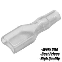
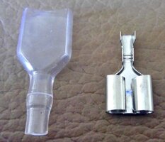
Some of the terminals from China are made of very thin material, most of them state the thickness of the material so you can compare. I've always soldered my terminals. My favourites are those horrid crimp connectors as in pic one, but I remove the coloured plastic, solder inside the crimping part, solder the bared cable and insert it.

When using bullets, I use the non insulated type, crimp them, then dab a little solder on the joint, before crimping the tabs around the wire insulation.

Depending on where the terminal us, I'll either use heat shrink or those clear plastic covers like in pic two.

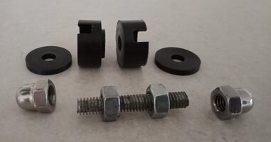
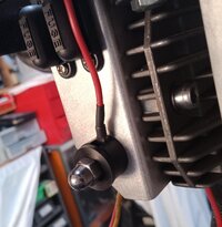
Can't say as I particularly like bullet connectors, the insulation tubes very rarely fit properly. I prefer blade terminals where possible or eyes for multiple connections via Delrin insulators I turn up on the lathe, as in pic three and four. Double bullet connectors can be handy in some places though, pic five.

Be very careful who you tell that you solder connections instead of crimping. The 'experts' will tell you crimping is better, soldering makes the copper wires harden and they will break, blah, blah, blah. And of course NASA use crimp connectors so crimping is obviously the best, blah, blah. Some crimpers get quite upset with solderers and will tell you you obviously don't know what you are doing.

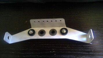
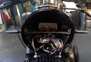
Last pics are of a terminal bridge I use inside the headlight bucket,. It doubles as an earth connection for multiple eye connectors and has a couple of Delrin inslulators I turned up for power connectors. You can also see quite a few bullets and double bullet connectors.

It's still very untidy inside the nightmare bucket though. Despite designing a simplified system consisting of two harnesses, one for lights, the other for ignition, there are still 30 plus connections inside the nightmare bucket. Just no way around it. From memory there are three cables in the ignition harness snaking its way up the frame and something like five or six for the lighting harness, on the other side.

The biggest problem was colour coding: Because I've used after market switches and controls, it's impossible to colour code everything, so, I've used green for earth and black for power and the rest as close as I could to match the colours.
 

Attachments

  • s-l1600 (3).jpg
    s-l1600 (3).jpg
    203.3 KB · Views: 14
  • s-l1600 (2).jpg
    s-l1600 (2).jpg
    107.6 KB · Views: 10
  • 2.jpg
    2.jpg
    89.7 KB · Views: 10
  • 5.jpg
    5.jpg
    215.4 KB · Views: 10
  • WIN_20220321_16_44_22_Scan.jpg
    WIN_20220321_16_44_22_Scan.jpg
    225 KB · Views: 13
  • 312403252_3399863606940328_2841076821273114446_n.jpg
    312403252_3399863606940328_2841076821273114446_n.jpg
    53.8 KB · Views: 13
  • 313347166_3399863720273650_6495409069037042857_n.jpg
    313347166_3399863720273650_6495409069037042857_n.jpg
    88 KB · Views: 14
Last edited:
Nice toglhot! I really like that bridge, neat and tidy.
I can bend one of those up at work easy. Thanks.!
 
Back
Top