Does My Stator Need Replacing?

abyssmaltailgate

Greenhorn Mechanic
Messages
148
Reaction score
9
Points
18
Location
Chicago
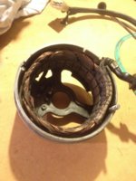
I'm going through everything on my first build, and the alternator's stator coils look really grimy. Take a look at the attached pictures; should I clean these, or do they need to be replaced?

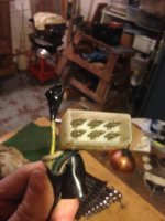
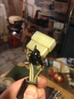
I can't find replacements on MikesXS (either that or I don't know what I'm looking at), but I've found some on motoparthub.com by Rick's Motorsports. Maybe it'd be worthwhile to send them to Custom Rewind for a rebuild? What are your opinions?

Also what's the best way to clean this part?
 

Attachments

  • 2015-11-18 15.21.08.jpg
    2015-11-18 15.21.08.jpg
    206.3 KB · Views: 243
abs...,

Don't clean the stator. The wires are 40 years old and cleaning can damage the wires. Just test them with an Ohmmeter on the lowest range that can measure less than 1 Ohm. Should be about .5 Ohms between any two of the three white wires after you have subtracted the resistance of the test leads, about .3 Ohm. Resistance from any of the white wires to the frame should be infinite, use the highest range for this test. Start with a known good battery in the Ohmmeter as you will get unreliable results with a weak battery especially on the low Ohms scale.
 
Thanks Pete! It sounds like all my wires and everything need to be put together and connected before testing. Is that correct?
 
Thanks Pete! It sounds like all my wires and everything need to be put together and connected before testing. Is that correct?

No, just the opposite, unless you have done something really gross to the wiring. If the stator is off the engine, then do the suggested tests. No need to reinstall for the tests.
 
First, it looks like I have 4 white wires. The end of my stator wires are arranged in some sort of plug with 2 rows of 3. One being blue/white/green, the other being white/white/white. There's also a yellow wire that's not in the plug that the previous owner put a piece of electrical tape over its end.

The resistance between the leads on the multimeter is 0.5. When I first tried reading the resistance between the white wires, I wasn't getting any reading. The meter stayed at 1, which I guess is the infinite reading. I cleaned the edges up a little bit, and the meter would not stop on a constant reading, it kept cycling through numbers. I had my friend, who is an electrical engineer play with it, and he ultimately did exactly what I did and we got readings of 0.9 and 1.0 across the white wires, subtracted by 0.5 that leaves 0.4 and 0.5 respectively... so I guess the stator's okay to use?
 

Attachments

  • 2015-12-03 20.13.03.jpg
    2015-12-03 20.13.03.jpg
    172.9 KB · Views: 211
  • 2015-12-03 20.11.52.jpg
    2015-12-03 20.11.52.jpg
    159 KB · Views: 242
First, it looks like I have 4 white wires. The end of my stator wires are arranged in some sort of plug with 2 rows of 3. One being blue/white/green, the other being white/white/white. There's also a yellow wire that's not in the plug that the previous owner put a piece of electrical tape over its end.

The resistance between the leads on the multimeter is 0.5. When I first tried reading the resistance between the white wires, I wasn't getting any reading. The meter stayed at 1, which I guess is the infinite reading. I cleaned the edges up a little bit, and the meter would not stop on a constant reading, it kept cycling through numbers. I had my friend, who is an electrical engineer play with it, and he ultimately did exactly what I did and we got readings of 0.9 and 1.0 across the white wires, subtracted by 0.5 that leaves 0.4 and 0.5 respectively... so I guess the stator's okay to use?

The blue wire goes to the neutral switch, the green wire goes to one of the brushes and that extra white wire should actually be black, goes to the other, grounded brush. The outer layer of insulation may have gotten torn off of it exposing the first layer of insulation.

Those numbers look good, just be sure to measure from any one of the white wires to the stator frame. Should be infinite on the highest scale.

As you reinstall the stator, be very careful and don't move the wires too much, especially do not bend them excessively. Try to maintain the original set that has been baked into the wires the past 40 years or so. I've changed a lot of rotors for rebuilt, but I have never had to replace a stator.

Now, the plug and connector are different as far as cleaning goes. Inspect all the terminals for any indication of overheating, such as melted plastic. Use a good contact cleaner and if you can, form a stick of folded very fine sand paper and insert that into the opening for each contact.
 
yep the black and green are clearly visible in your pic the yellow wire WAS power to the headlight safety relay, a device often removed. As long as the unit is off the bike pay attention to the wire harness where it passes under the sprocket, it's a nasty environment, broken and shorted wires do happen there. Check continuity on the green and black wires also. When installing the stator note that there is a small pin sticking out of the lower crankcase at about 7 o:clock, it fits to a slot in the stator. The charging system guide is a good read. Check brush lengths, and ohm out the rotor slip rings, a failed rotor is much more common than a failed stator. While you are doing electrical checks run the diode test on the rectifier.
 
Back
Top