help with wiring diagram

mapster

XS650 Member
Messages
16
Reaction score
0
Points
1
Location
MA
Hello XS650,

(I posted this in the tech thread "some wiring diagrams" but I'm not sure that get much traffic so I thought I would start a thread)

Would anybody care to take a look and critique my wiring diagram?

1982 Heritage Special
stock TCI
stock alternator
kickstart only

My first attempt at this so I apoligise if its confusing. I just tried to eliminate criss-cross wires, they make my head spin. Didn't really put too much thought into wire colors yet.

All lighting, aside from the headlight, will be LED. Also, I just realized my indicator light need ground. I will add those in the next draft.

Thanks!
:bike:

full
 
Hey mapster, clean schematic

- 6 lines plus ground coming off alternator? (You've already got brush & pick-up)
- Does alternater have a ground, the stator doesn't ground, brushes don't either.
- Total of 10 lines for reg/rect?
- GND symbols for plugs
- Turn signal & ind lits should show T-shared lines (brn & grn), not pass-thru. Like you've done the GND
- Will the flasher relay do LEDs, or need an add-on load contraption?
- Does this model have only 1 GND cable for battery?

(Fussy, fussy - I used to be a sch checker)

I don't know anything about heritage models - my 2 cents

This will be real handy for those guys looking for simplified diagrams...
 
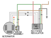
that's 3 white wires off the alt not 6 lines, but what's handle switch LED? the electronic flasher shouldn't need any load add-on, other wise what's the point, take away resistance from the bulbs and then add it back with a resister? alt/brushes don't use a ground on the 80 and later TCI models ... electrically his drawing is the same as this one
 

Attachments

  • untitled.PNG
    untitled.PNG
    3.9 KB · Views: 192
Hey mapster, clean schematic

- 6 lines plus ground coming off alternator? (You've already got brush & pick-up)

Might be an optical illusion. There are only 3 white wires coming off the alternator. Might help if I add a gray backround.

- Does alternater have a ground, the stator doesn't ground, brushes don't either.
- Total of 10 lines for reg/rect?
- GND symbols for plugs
- Turn signal & ind lits should show T-shared lines (brn & grn), not pass-thru. Like you've done the GND
- Will the flasher relay do LEDs, or need an add-on load contraption?

Yes, LED flasher

- Does this model have only 1 GND cable for battery?

(Fussy, fussy - I used to be a sch checker)

I don't know anything about heritage models - my 2 cents

This will be real handy for those guys looking for simplified diagrams...

Thanks for the input TooMany! Couple answers in red above. Jayel also added his input which is much appreciated. I just realized the diagram hanging in my garage that I have been studying for a month is one of his, lol. I wont be able to update the file until Monday. I will post an updated diagram then.

jayel, my new handle switch is backlit.
 
I've been using a Samsung 8.9 tablet for all this forum stuff, maybe it doesn't show CAD drawings right. The backround of your sch shows pure white, and I can't see anything other than pure white for the stator wires, so all I saw was 6 thin black lines. Jayels sch has a light tint to his white wires, I can see those. Good that the XS flasher handles LEDs. I was researching LEDs awhile back, and many auto applications had to use loading devices, even when using 3-pin flashers, and like jayel said: 'what's the point?'.
Jayel, need to fix your rectifier, the white wires each tap into the middle their diode pair...


Just to clarify, I'm using an aftermarket flasher. It's my understanding the stock flasher would require adding inline resistors to function properly.

:thumbsup:
 
Well, I'm only familiar with 3 types of flashers.
1 - Common 2-pin flashers that have a heater that warms-up a 'oil can' contact arm. This 'arm' is bi-metallic, expands/curves in one direction when warmed-up, but is bent, like the bottom of old oil cans, so that it 'pops' to a second shape. A contact point is on the end of this 'arm', similar to a relay arm or 'throw'. The common version works properly on 4-bulb turn signal systems (2 bulbs at a time). The heater and contact switch are in series, and in series with the 'parallel' turn signal bulbs. The current draw of the bulbs defines how hot the heater becomes, which how fast it flashes, if at all. Too many or too few turn signal bulbs, or bulbs of different wattage, may cause the flasher to flash too fast, not at all (like when using LEDs), or overheat/burnout.
2 - Heavy duty 6-bulb version of above. Same device, handles more current, like when pulling trailers. May not work well on 4-bulb systems.
3 - Self heated 3-pin flasher, modern version. Heater current somewhat independent of load, better system. Some of these don't play with LEDs.

There are others, louder, quieter, heavier loads, LED specific...
Now we have LED-specific solutions, involving adding dummy loads.

I don't know much about these other modern variants. But there is some confusion in the consumer community, as some auto 3-pin variants don't do LEDs well. That's why I brought it up. I don't know if the Yamaha flasher has this issue or not...
 
Jayel, need to fix your rectifier, the white wires each tap into the middle their diode pair...

Artistic license :laugh: represents more of a idea, "not intended to be factual statement", if politicians can get away with it so can I :D .... a LED flasher that uses the wizardry of transistors/capacitor charge time, doesn't need the extra loads, it is said science we do not understand might as well be magic, so get 1 of them thar magicly flashers and be done with it
 
Last edited:
If I send you my wiring diagram, will you make me one of those drawings?

Just kidding.

Would love to be able to do that.

:thumbsup:
 
If I send you my wiring diagram, will you make me one of those drawings?

Just kidding.

Would love to be able to do that.

:thumbsup:

Thanks man! TBH I thought I was going to get laughed off the forum.

Question(s): The fuse panel I'm looking at is 6 fuses rated @ 65 amp max. My current configuration is 6 fuses @ 70 amps. Would I be OK connecting a 5 amp fuse to the blue wire coming of the main switch or does anybody see a better way to eliminate a fuse? Should I look for a fuse panel with larger capacity?
 
Your fuse panel will be fine I think. You won't be pulling 70 amps through it ever, a fuse would blow first.

Think of your home breaker box. Panel will be rated for something like 100 amps, but if you count the total of the breakers it'll be over 100.
 
Thanks man! TBH I thought I was going to get laughed off the forum.

Question(s): The fuse panel I'm looking at is 6 fuses rated @ 65 amp max. My current configuration is 6 fuses @ 70 amps. Would I be OK connecting a 5 amp fuse to the blue wire coming of the main switch or does anybody see a better way to eliminate a fuse? Should I look for a fuse panel with larger capacity?

Your fuse panel will be fine I think. You won't be pulling 70 amps through it ever, a fuse would blow first.

Think of your home breaker box. Panel will be rated for something like 100 amps, but if you count the total of the breakers it'll be over 100.
Trance is right, you'll be fine with what you have
 
Back
Top