PAMCO Wiring

rickrman

XS650 Enthusiast
Messages
85
Reaction score
49
Points
18
Location
South Dakota
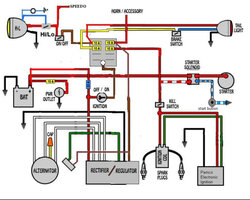
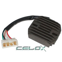
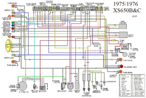
Dear Peeps, Will this diagram work with a 7-wire combination rectifier/regulator and stock alternator? Is the brown wire split to the alternator brushes and the load as pictured?
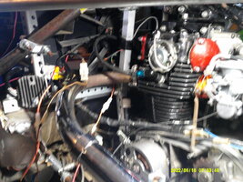
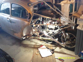
The juice keeps going around in my brain and I would hate to smoke my new ignition. Thanks for the consideration of my request. Project pictures to follow soon.
 

Attachments

  • coee.jpg
    coee.jpg
    57.8 KB · Views: 50
That will work for a '80 and later US alternator and regulator set-up
 
Nope, the OEM Stator/rotor will work just fine with a PAMCO, the brushes just need matched with the style of regulator: a "ground regulating" regulator (late model), or "power regulating" (early pre '80). Your diagram shows a late model regulator
 
There are aftermarket, solid state regulator/rectifier combos that are "power regulating" available to use and retain the original brush wiring for an early model "points style" rotor brushes. Diagram looks like this:

77_XS650D (2).PNG

Black brush wire is tied to harness ground and green carries power. On later systems Brown brush wire is tied to switched power and green is providing regulated ground via regulator
 
Last edited:
There are aftermarket, solid state regulator/rectifier combos that are "power regulating" available to use and retain the original brush wiring for an early model "points style" rotor brushes. Diagram looks like this:

View attachment 236233
Black brush wire is tied to harness ground and green carries power. On later systems Brown brush wire is tied to switched power and green is providing regulated ground via regulator
So I can leave my brushes grounded and just run the brown wire from my after-market regulator/rectifier to the load?
 

Attachments

  • coee.jpg
    coee.jpg
    84.4 KB · Views: 40
Last edited:
So I can leave my brushes grounded and just run the brown wire from my after-market regulator/rectifier to the load?
We have to know what model regulator/rectifier is present and what stator/brush wiring currently exists to definitively answer that - link, instructions on the former; pics of the latter. On an old system only one brush is grounded, on late system neither brush is grounded (fully).
 
I have a cheap aftermarket rectifier/regulator with 7 wires. 3 white, red, green, black and brown. I have the black regulator/rectifier wire to the stock brush and grounded together. I have the red to positive, the green to the brush, whites-to whites and brown to load. I feel like something is wrong but I have fuses everywhere so maybe I should try it? My engine originally had points. JP, you are a saint.
We have to know what model regulator/rectifier is present and what stator/brush wiring currently exists to definitively answer that - link, instructions on the former; pics of the latter. On an old system only one brush is grounded, on late system neither brush is grounded (fully).
 

Attachments

  • Proposed1.jpeg
    Proposed1.jpeg
    112.7 KB · Views: 46
Last edited:
So the problem is: we (I) don't know how your brushes are situated and both types of regulator/rectifiers can have 7 wires in the colors you have listed. Do you know the source and p/n for the regulator?
 
So the problem is: we (I) don't know how your brushes are situated and both types of regulator/rectifiers can have 7 wires in the colors you have listed. Do you know the source and p/n for the regulator?
Alternator is stock from original points-type engine. Rectifier/regulator is so cheap, it has no number. https://www.ebay.com/itm/271515149496
 

Attachments

  • s-l500.jpg
    s-l500.jpg
    22.3 KB · Views: 45
  • update.JPG
    update.JPG
    418 KB · Views: 43
  • update1.JPG
    update1.JPG
    419.4 KB · Views: 42
Alternator is stock from original points-type engine. Rectifier/regulator is so cheap, it has no number. https://www.ebay.com/itm/271515149496
My guess is that's a "ground regulating" unit (US listing says XS650 '78-83 and can't be right for US). So, both brushes need to be isolated from ground (nylon screw trick) and black brush wire connected to brown (brown also to switched power) and green brush wire to green from regulator. All best guesses......
 
My guess is that's a "ground regulating" unit (US listing says XS650 '78-83 and can't be right for US). So, both brushes need to be isolated from ground (nylon screw trick) and black brush wire connected to brown (brown also to switched power) and green brush wire to green from regulator. All best guesses......
JP, can you add a link to the nylon screw trick? Will I have to pull the stator to trick it? Thanks again! Maybe this instead? It calls for Points. https://www.ebay.com/itm/162015197369?fits=Model:XS650|Make:Yamaha&epid=171150252&hash=item25b8dbb8b9:g:xHUAAOSwxDBdG8u5&amdata=enc:AQAHAAAAwGkFC8CwoOmybczjdG4rm8bYUzKBuakck6Q1Fze1skyGrfYP9oiT04tMEO6AuqW6FPZiYIQcFS919a5xy5yvy4cc8sqiQpb0/KElCAVvCVrMxihimI/lwV8KtJPx83Lw81C+c62TITi++UTxQhTUj5pLBtehxOPp3s6T6ucqBoIpuDnNb13Q0bkGvuyQfcgVPNexW+BkWZv9UQb8gwauQV4UK5OewJEmX0oz4XtJ4lSUNQomIOabDlHcwI1YsU1Duw==|tkp:Bk9SR4iO7fvPYQ
 
Last edited:
That last regulator is a "power regulating" model and wires-up like a std points XS-70-79 US.

All the Nylon Screw threads are a little rambling, basically replacing 3 of 4 brush holder screws with nylon screws (bottom left stays metal)
https://www.xs650.com/threads/nylon-screws.6477/page-4#post-591980

If unknown, safer to assume a late model regulator, install nylon & test, once connected, for magnetism @ rotor - go from there..
 
Thank You for the link. I will proceed with the trick. There is no easy way to run a PAMCO with a stock pre-80 alternator and after-market cheapo regulator/ rectifier. I (we) should invent a harness adapter to plug-and play a cheapo rectifier/regulator to a stock alternator harness. The stock alternator harness blue wire going to ground may be involved? Thinking...thinking....
 
The harness light blue at the stator connector is neutral switch on top of crankcase. PAMCO connects the same no matter the charging system.
 
The harness light blue at the stator connector is neutral switch on top of crankcase. PAMCO connects the same no matter the charging system.
One of my many wiring diagrams shows the blue wire connecting to the neutral light circuit and tied into brown wire. See upper left. Since blue is intermittent ground, the brown is energized AND grounded through the combination cheapo regulator/rectifier? Why is this so hard? Why am I so confused? Thinking and smoking out of my ears. The brown wire must also have an additional battery source other than the rectifier/regulator? Perhaps.
 

Attachments

  • 75_76_XS650 B&C Wiring.PNG
    75_76_XS650 B&C Wiring.PNG
    60.8 KB · Views: 38
Last edited:
Thank You for the link. I will proceed with the trick. There is no easy way to run a PAMCO with a stock pre-80 alternator and after-market cheapo regulator/ rectifier. I (we) should invent a harness adapter to plug-and play a cheapo rectifier/regulator to a stock alternator harness. The stock alternator harness blue wire going to ground may be involved? Thinking...thinking....

Yes there is.

Points ignition models, (70-79 US/Canada/Japan and 70-83 in most other countries in the world), have separate Regulators and Rectifiers.

When buying a Combined SolidState Reg/rect for a points model bike they usually have wiring with 2 pigtails and connectors to connect straight into the factory harness. Some have the wires loose to be split and made up by the installer.

Using a Pamco ignition on a points model bike, the 2 coils need to be swapped for a single output coil. as mentioned


Buying the wrong Reg/Rect creates confusion and problems.........If the Reg/Rect has a single 6 pin connector this usually indicates it is for a Factory Electronic ignition, (TCI), model.......80-83/4 US/Canada/Japan
 
Last edited:
Yep, the brown is power to the neutral bulb in dash and switched ground (light blue) is provided by the neutral switch. Brown also exits fuse box and sends power to the regulator (brush is spliced in parallel from brown, late model regulator) and powers various other things (signal flasher, etc)
 
Yep, the brown is power to the neutral bulb in dash and switched ground (light blue) is provided by the neutral switch. Brown also exits fuse box and sends power to the regulator (brush is spliced in parallel from brown, late model regulator) and powers various other things (signal flasher, etc)
I think I understand. This configuration requires the "nylon screw trick" to the black wire brush side which is then connected to brown wire which is then split with one to switched power and one to load?
 
Yes there is.

Points ignition models, (70-79 US/Canada/Japan and 70-83 in most other countries in the world), have separate Regulators and Rectifiers.

When buying a Combined SolidState Reg/rect for a points model bike they usually have wiring with 2 pigtails and connectors to connect straight into the factory harness. Some have the wires loose to be split and made up by the installer.

Using a Pamco ignition on a points model bike, the 2 coils need to be swapped for a single output coil. as mentioned


Buying the wrong Reg/Rect creates confusion and problems.........If the Reg/Rect has a single 6 pin connector this usually indicates it is for a Factory Electronic ignition, (TCI), model.......80-83/4 US/Canada/Japan
The cheapo regulator/rectifier has 7 pin connectors. Thank You for the help. I think JP has it correct.
 
Back
Top