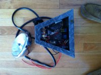
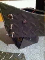
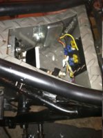
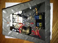
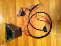
I've started to hook up wiring for my brat build. Its a 76 xs650. I modified the frame and built a electronics box to fit below the seat like so many do and then hung a battery box below the electronics box, All cut and welded from thin diamond plate steel then powder coated. In side the box I mounted a fuse block with 6 spaces, a vr-155 regulator a 3 phase rectifier, original starter relay. On the out side of the box I drilled holes for and mounted a small push button for exciting the starter relay below it the main power on/off switch and below that my light switch.The 2 switches are 30 amp commercial type made in Mexico of good quality. The battery is a Shorai battery with more caa than original.
I bought a cheap handlebar switch for the left side with hi-low beam for headlight, blinker that Im using for my kill switch and a horn button. I bought a 5.75 chrome aftermarket headlight. In the headlight I will
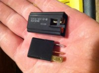
pull all my wiring for the headlight horn and kill switch. Im using 2 small Japan made relays on a 30amp spdt for headlight and a 20amp for horn. I did not want to put to much current through the cheap handlebar unit.
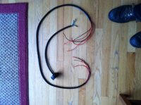
I ran 5 wires in a pvc sleeve for power and ground and kill switch.
I took two 14ga wires for power going up to power the light and its relay and horn and its relay.
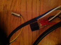
I bought oem type bullet connectors and spade type connectors and the tool to crimp the wires in them.
The way I wired the headlight relay was to run the 14ga to double bullet connector then to terminal 30 of the spdt relay in the other spot of the double bullet connector I ran up to the hi-low beam selector of the handlebar switch and back down from the handlebar switch to the terminal 86 on the relay. That way when I turn on the high beams the 12vdc goes through the handlebar switch to excite the relay on 86. causing the switch to close and then power is directed to terminal 87 of the relay and goes to the high beam of the headlight. Nice thing about a spdt relay is that terminal 87 is normally closed so I hooked up the low beam to 87 so I do not need 2 12vdc wires to control it or even 2 relays. On terminal 85 I hooked to my 3rd 14ga wire going back to the electronics box where it is bolted to a stud along with ground strap from negative battery terminal. I also used a trippler bullet connector for all the grounds needed. Back down in the electronics box I used a doubler for the lights with one bullet connection for headlights and one for tail lights. I will run a separate brake light as I want them to work even if the headlight is off. I have not completed the horn and kill connections as of yet but will do so in the near future.
The kill switch is 2 16ga wires running up to the bucket then to the turn signal switch on the handlebars. Im using the left turn signal as the closed circuit so the bike wont start unless Ive got the left blinker on. I wont have blinkers but Im just using that switch. And when I move that blinker switch to center or right position the bike will shut down. The 12vdc will run up to switch then back down the second 16ga wire to excite a relay and close the 7.5amp circuit for the pamco and coils.
The horn will have a relay in headlight bucket also. Circuit somewhat like the lights but only a spst relay like the one for the ignition circuit.
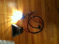
The start relay is just power coming from the main on-off switch to the fuse block to the small momentary push button to the hot trigger red/white wire already on the stater relay and the blue and white wire going to ground lug in the box. I made most of the connections today out of the bike to test it out and the start solenoid works good and head light as it should. Did not smell anything burning so the smoke test if over for those 2 circuits.
Ill add more as I progress.
I bought a cheap handlebar switch for the left side with hi-low beam for headlight, blinker that Im using for my kill switch and a horn button. I bought a 5.75 chrome aftermarket headlight. In the headlight I will
pull all my wiring for the headlight horn and kill switch. Im using 2 small Japan made relays on a 30amp spdt for headlight and a 20amp for horn. I did not want to put to much current through the cheap handlebar unit.
I ran 5 wires in a pvc sleeve for power and ground and kill switch.
I took two 14ga wires for power going up to power the light and its relay and horn and its relay.
I bought oem type bullet connectors and spade type connectors and the tool to crimp the wires in them.
The way I wired the headlight relay was to run the 14ga to double bullet connector then to terminal 30 of the spdt relay in the other spot of the double bullet connector I ran up to the hi-low beam selector of the handlebar switch and back down from the handlebar switch to the terminal 86 on the relay. That way when I turn on the high beams the 12vdc goes through the handlebar switch to excite the relay on 86. causing the switch to close and then power is directed to terminal 87 of the relay and goes to the high beam of the headlight. Nice thing about a spdt relay is that terminal 87 is normally closed so I hooked up the low beam to 87 so I do not need 2 12vdc wires to control it or even 2 relays. On terminal 85 I hooked to my 3rd 14ga wire going back to the electronics box where it is bolted to a stud along with ground strap from negative battery terminal. I also used a trippler bullet connector for all the grounds needed. Back down in the electronics box I used a doubler for the lights with one bullet connection for headlights and one for tail lights. I will run a separate brake light as I want them to work even if the headlight is off. I have not completed the horn and kill connections as of yet but will do so in the near future.
The kill switch is 2 16ga wires running up to the bucket then to the turn signal switch on the handlebars. Im using the left turn signal as the closed circuit so the bike wont start unless Ive got the left blinker on. I wont have blinkers but Im just using that switch. And when I move that blinker switch to center or right position the bike will shut down. The 12vdc will run up to switch then back down the second 16ga wire to excite a relay and close the 7.5amp circuit for the pamco and coils.
The horn will have a relay in headlight bucket also. Circuit somewhat like the lights but only a spst relay like the one for the ignition circuit.
The start relay is just power coming from the main on-off switch to the fuse block to the small momentary push button to the hot trigger red/white wire already on the stater relay and the blue and white wire going to ground lug in the box. I made most of the connections today out of the bike to test it out and the start solenoid works good and head light as it should. Did not smell anything burning so the smoke test if over for those 2 circuits.
Ill add more as I progress.

") for me it is as a novice in Electrics as of yet
for me it is as a novice in Electrics as of yet