sleddog83
XS650 Addict
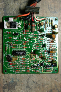
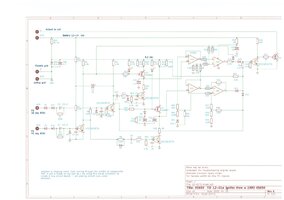
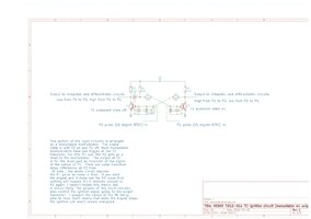
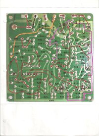
I have been collecting this information for a while. Finally getting around to posting it. I don't think this stuff is stored in the tech section. The picture of the bottom of the circuit board was done when I was reverse-engineering the board. I thought it might be useful for anyone who is doing some troubleshooting. The board works similar to the 12-03 board in that it creates a couple integrator waveforms that it compares for the advance timing. I have changed the resistors at R22/R23 and R14/R51 to correct the advance curve on my board, but the values listed on the schematic were what it came with. Other boards may be different. I suspect they were "fine tuned" at the factory. I also replaced C5. I am not sure what the factory value should be, but I have a 10uF on the board right now. This was an oops on my part. I missed the cap during the reverse-engineering process then subsequently removed and lost it when I was doing some bench testing of the board. The 10 uF seems to work, but if anyone knows what should be in there let me know.
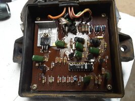
The board I have is my backup board as well as bench test board that I try out different stuff on, so it is a little hacked up. A note of caution with this version of board. The circuit board traces are quite delicate. It doesn't take much heat to rip the traces right off the board. Takes a good soldering iron and a delicate touch.
A couple of other things to note. I have successfully used the ST901A as a substitute for the output transistor(PTR1) on this board. I have been unable to find original replacement transistors for T1 and T2. I have found a substitute KSC1845 that I think will work okay, but haven't tested them on this board yet.
Attachments
Last edited: