Wiring Help!!! Pamco, 79 with 80+ reg/rect combo

hutch08

XS650 Addict
Messages
157
Reaction score
0
Points
16
Location
CANADA
Wiring Help!!! Pamco, 79 with 80+ reg/rect combo .. XSLeo?

Hey,
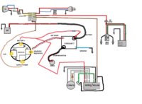
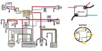
This attached wiring diagram is the one that I'm going to use on my chop, but I have a few questions about it.

My bike is a 79, with PAMCO, 80+ reg/rect(replaced screws with nylons) & electric start.

1. On the diagram for the alternator to rectifier it shows all the same colored wires... on my alternator side theres : 3 White, Black, Green, and Yellow
my Reg/Rect side theres : 3 White, Black, Green, Red, and Brown.

How do they wire up together???

2. I'm confused about the starter solenoid wiring, it has 5 wires:
2 large black wires on opposite corners
Red with white stripe
Blue with white stripe
Soild red thats tied into one of the black wires

How is that supposed to be wired?

3. I want wire a keyed ignition to control the power of everything, it has off/acc/on/start functions, on the back it has 4 terminals: B, ACC, IG, ST

How do I wire that up so when I turn it on, I can crank the starter with the key?
I dont need the ACC function right now, maybe later I'll use it if I add an AUX output or something...

4. Does the PAMCO matter which wire goes to + or - on the coil?

Sorry for the dumb questions but I'm kind of boggled by all this...

I'll also be using all inline fuses to make things a little easier and not have to worry about mounting the fuse panel.

If anyone wants to modify my original wiring diagram go right ahead, it'll just make my life easier.

Please and Thank-You!!!
 

Attachments

  • wiring6.jpg
    wiring6.jpg
    158.2 KB · Views: 957
Last edited:
The starter solenoid wiring has that extra red probably as a source for battery power as one of those black wires comes directly from the battery and the other goes to the starter.

To wire the start function of the switch you would have to ground the blue/white wire and probably connect the red/white to the start terminal of the switch. Check the switch to make sure you have continunity between the bat and start terminals when the switch is in the start mode.

I thought about doing that at one time but seemed better to have the start button at the bar if you should accidently snub it in the middle of an intersection (not that I did that, LOL)

Pamco I don't think matters which side goes where.

can't help on the rec/reg
 
I don't see a starter switch.
 
Ok on my 79, it has a black wire from battery positive directly to the starter solenoid to provide big cranking amps to the starter when the solenoid is activated.

The red wire from that same battery positive splits off and feeds your main fuse at the fuse box.

The red white is a return from your ignition that feeds power to the starter solenoid when the key is switched on.

The blue and white is the ground return from the starter button. when you hit the button it grounds on the handlebar and completes the circuit for the starter solenoid with the red/white, allowing the solenoid to make contact and allow big cranking amps from the big black battery positive wire to flow across to the big black wire that goes down to the starter, spinning the starter and starting the fun.

On your alternator, the yellow wire sends a charging signal to your safety relay and the safety relay "sees" it and allows the headlight to burn (since the motor is now running and charging and all the amps aren't needed to crank) and stops the starter from turning needlessly now that the bike is cranked.

For your new ignition switch with start function, maybe the blue/white should be wired to the start terminal of the switch so that when you key it up it is grounded and completes the circuit?
 
Ok, so the starter solenoid now makes some sense, black with red to battery, black to starter, red to feed power, red with white to keyed on, blue with white to keyed start? Does that make sense? Or should the red with white go to keyed start and blue to ground?

And what about that reg/rect combo wiring?
 
The blue/white wire going to the solenoid is normally ground and the red/white is 12v with the key on with the stock wiring. When you push the stock starter button it grounds the blue/white wire and because you have 12V at the red/white on the solenoid it activates the solenoid and sends current from the battery through the solenoid down to the starter.If you connect the blue/white to the start terminal of the switch you will be sending 12V to the ground side of the solenoid when you have the keyed switch in the start position. It may work if you ground the red/white but not sure. I don't see how you could get ground from the ignition switch as suggested. Blue/white to ground and red/white to start terminal of the switch should work.
 
Thanks grinder! That should definitely work for the starter solenoid & keyed switch! i hope anyways, at least it makes sense, instead of completing the circuit by grounding the blue wire, i'll be completing the circuit by energizing the red/white wire.

So for the ignition, the IGN I would assume go to power the bike, like keyed on.
The ST would be the red/white wire to the solenoid.
ACC wont be used right now.
and the B is power from the battery??? Sound right to anyone?

Also whats the deal with the reg/rect? Im sure someone has used a newer combo unit on an pre 80's xs650.
 
Your switch plan sounds like it should work. Check post 16 here by XsLeo, it may shed some light into your rec/reg problem.
http://www.xs650.com/forum/showthread.php?t=6477

Thanks! I think you just helped me bigtime,
quote XSLeo "On your reg/rec the three whites go to the three white on the stator, the red to battery positive, the black to battery negative, the brown to power after the key switch, the green wire to the green wire to the stator.
The brown wire from the stator goes to power after the key switch. Often peolpe hook the brown wire from the stator to the brown wire from the reg/rec together and run a brown wire from that connection through a fuse and hook it to power after the key switch."


Only dilemma I have now is that on my stator i doesn't have a Brown wire, its Black. So am i to presume that the black from the Stator will go to the brown on the reg/rect then to keyed power?
 
Now dont laugh... I threw this together in 30s, haha does this "modified" diagram look like it will work?
 

Attachments

  • wiring7.jpg
    wiring7.jpg
    234.4 KB · Views: 322
Looks good. I might use just one fuse for both the head and tail lights. I might also suggest using the 7.5 amp fuse that Pamcopete suggests for the ignition.
I think you said you have the nylon screws replacing the screws for the black wire brush. You need to do this. The 80 up reg/rec needs the nylon screws.
Leo
 
Back
Top