wiring help

huey224

XS650 Enthusiast
Messages
56
Reaction score
1
Points
6
Location
duff,tn
ok I have a 83 xs650 bobber style i just traded for all i am wanting to do is make it charge and run for now the wires i have coming out of my stator cover are 3 white 1 yellow 1red and 1 green. the wires on my box are 3white 1green 1red 1black and 1 brown? he had the plug cut off and just wired together does it matter which white goes to which one? correct me if im wrong (green with green) (black with black to a ground on frame) (red with red) then red to battery? i have read all the wiring diagrams but they show a brown wire coming out of stator someone please help me:banghead:
 
well the only wire im having problems with is all the diagrams say a brown wire from the stator i dont have one i have a red wire its the trouble maker lol
 
perhaps your bike has been fitted with a stator from an earlier bike . The 83 schematic shows the 12v+ supply to the rotor being fed by a brown wire from the battery.
On the earlier rotors its fed by a red wire.

Depending on how much your bike's wiring has been hacked you've probably got a 12v+ brown wire direct from either the battery or the fuse box going to the rotor/stator connector and that should connect with the red wire which comes from one of the rotor brushes.

The yellow wire goes to the safety relay if fitted and prevents the starter operating when the engine is running.if you don't have a starter fitted leave the yellow wire unconnected.

On my schematic the green wire is shown earthing through the neutral switch so it must be some sort of inhibiter.?

Tell us the colour of all the wires coming from the stator/rotor and all those on the connector from the loom and it will help us sort it out
 
well of course the 3 white wires going to the 3 white wires in the connector to the ignitor unit or cdi or whatever it is lol the finned box with 7 wires coming out of it to a connector then i have a green going to a green in the connector then a yellow that is unhooked then a red coming out of the stator not hooked up on my plug in I have a red a black and brown left unplugged thats where im confused im guessing black to ground but what about the red and brown wire and the red wire left on my harness which one does it go to? would the red wire go to the brown on connector then red from connector go to battery?
 
sorry that description is too confusing for me to make any sense of it. You are going to need to provide a picture if we are able to help you.:)
 
Ok the XS650 never in it's life ever had a CDI, it uses a TCI but those are ignition systems and have nothing to do with charging.
The reg/rec is a 7 wire unit with a finned aluminum body. The TCI is a plastic box with either 6 or 7 wires. The reg/rec is mounted to the frame just behind the engine. The TCI box is mounted on the bottom of the battery box. Well that's on a stock bike. On yours having been bobbed they can be put anywhere.
On the 80 up bikes they all used the same reg/rec It has 7 wires 3 white, black, red, green and brown.
Out of your stator there are 5 wires, 3 white, a green and a brown. Now to hook the two together you hook the three whites to the three whites.
From the stator you hook the green to the reg/rec green. On the brown wires you hook them together then run a brown wire from this joint to power after the main switch.
From the reg/rec you should hook the red to battery +, the black to ground.
The way your alternator works is power is fed on the brown wire to the reg/rec, this is a voltage sencing wire. The reg uses this voltage reference to determine what the battery voltage is. If low it charges the battery if ok it won't.
The brown wire to the stator feeds battery voltage to the brush, from the brush through the rotor, out the other brush on the green wire to the reg/rec.
When the reg/rec sences a low voltage on the brown wire it grounds the green wire to let power flow, This power flow creates the magnetic feild the stator needs to create electricity. When the voltage on the brown wires reaches 14.5 volts the reg/rec ungrounds the green wire, cutting the power flow so no charging.
It cycles the power through the rotor on/off to keep the battery voltage at 14.5 volts.
Oh, peanut the rotor was never fed on a red wire. The early bikes with the mechanical reg, power went to the reg on a brown wire. The reg used this brown wire as both a voltage sencing wire and a power feed to the rotor. When it senced low voltage it sent battery voltage out on the green wire to the brush, through the rotor to the other brush where it was grounded to the stator housing with the three steel screws and out on the black wire to the harness ground.
Leo
 
Now to your ignition. If it still has the stock TCI then on the stator is an oval black unit. This is your ignition pick ups. It gets triggered by a magnet mounted in the rotor. When the pick ups sence the passage of the magnet it sends signals to the TCI box. The TCI box uses these signals to determine the crank position and rpms. It needs this info to determine when to make the plugs spark.
Yours being an 83 it has a 7 wire TCI box. The 7 wires from the TCI box are orange, two red/whites, green/white, black and two black/whites. In the stock wiring there was a three wire plug on the pickup that plugged into a three wire plug going to the TCI bo. These wires were one of the red/whityes, one of the black/whites and the green/white.
The second red/white went to power after the switch. The same red/white wire that the coil hooks to.The orange goes to the coil. The black to ground. This leaves the second black/white wire, this went to the sidestand relay. When the sidestand is down and you put the bike in gear the relay grounds this black/white wire and stop the TCI from working, shutting the engine off.
Being your bike is a bobber I doubt you have the sidestand switch or relay on the bike. If this is so this second black/white wire gets capped off.
If you look in the tech section for electrical diagrams you will see just how the ignition and reg/rec are wired. I like diagram #4. It shows the basic points diagram with the later TCI and reg/rec in boxes, just swap boxes to match what you have.
Leo
 
ok ive done all that but the i do not have a brown wire coming from stator it is red but i do have the brown wire from the reg/rec so just hook those two together?
 
also i took my cover off and was looking at the stator and there is like nylon screws instead of steel ones in the brush assembly.should i put steel ones back in?
 
If it is an old style stator then to use the later combo reg/rec then it needs the nylon screws.
Your wire from the stator will be one of two colors. The older it was black, the later was brown. It my look red but it's brown. Unless it is a rewound stator then the wires may be any color.
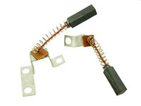
Another thing that you can look at are the brushes. In these pics you can see the difference The top first set is a 70-79 set, the second is the 80 up. You will see that one set they are both the same and the other set are not the same. The set that is the same is an 80 up set. The set with one brush having a much longer mount strap is for the 70-79 stators.
Leo
 

Attachments

  • 24-2650.jpg
    24-2650.jpg
    8.3 KB · Views: 59
  • 80 up brushes.jpg
    80 up brushes.jpg
    2.9 KB · Views: 154
Oh, peanut the rotor was never fed on a red wire. The early bikes with the mechanical reg, power went to the reg on a brown wire.
Leo

I know :D

if you re-read my post you'll see that i clearly state that it is fed by the brown wire. My reference to the red wire was supposed to be in relation to the regulator/rectifier supply . It was very late at night and I was tired and I wasn't paying attention to what I was typing I suppose .

The way i read the initial post was that the bike was a bobber and had clearly been hacked about before the current owner bought it so there was no way to be sure what components had been fitted to the bike and from what model year :wink2:
 
i hooked it all up how you said to and checked voltage before starting battery was 12.00 volts i had my helper hold the meter on it turned the key on it droped to 11.7 volts started it up let it idle for a bit it dropped to 11.2 then back up to 11.9 when i shut bike off it red 11.9 volts so does this mean its charging? also my keyswitch has three wires coming out of it a brown,red and blue ive got the red to battery and blue to headlight and coil but whats the brown wire for? it reads no voltage it does nothing what's it for?
 
i hooked it all up how you said to and checked voltage before starting battery was 12.00 volts i had my helper hold the meter on it turned the key on it droped to 11.7 volts started it up let it idle for a bit it dropped to 11.2 then back up to 11.9 when i shut bike off it red 11.9 volts so does this mean its charging? also my keyswitch has three wires coming out of it a brown,red and blue ive got the red to battery and blue to headlight and coil but whats the brown wire for? it reads no voltage it does nothing what's it for?

With engine idling, you should have about 13 to 13.4 volts, so you are not charging. Rev the engine to 3000 rpm to see if the voltage goes up..................looking for >14 volts.

The brown wire should have voltage when the key is on. Its rather important for the charging system as it powers the rotor + brush (right brush) and also is the reference voltage to the rec/reg. The brown normally supplies power to the 3 load fuses. The blue normally powers the tail light and meter lights.
 
yeah i revved it it went from 11.2 volts to 11.9 i guess i need to take cover off and test some stuff any suggestions and the guy i got it from told me its all 83 factory stator and stuff he just redone engine.
 
ok i took my brushes out and one was in god shape the other the spring was broke and cooked and wire rusted real bad so i guess it wouldnt hurt to buy new ones and start there i tested all my white wires and they all ohmed out good and around the same and read infinity when touched to ground. how do i test the windings to make sure they are good?
 
Ok The 3 white wires hook to the windings of the stator, so doing the ohms test is checking the stator windings.
To test the rotor windings you test of one slip ring to the other slip ring and from the slip rings to ground.
If you have the brushes out it makes it easier to test the rotor. THe one slip ring is easy to get to, the other is behind the brushes and part of the stator housing. You can't even see it.
With the brushes out you can use a piece of wire, like a paper clip, straighten it out, wrap the wire around one of the probes to reach down through the brush holder to reach the rotor slip rings.
You should get 4-6 ohms from slip ring to slip ring and infinity to ground.
Was the brush with the bad spring hooked to the brown wire? If so you may find a bad rotor.
Power is sent to the brush on the brown wire. If the rotor is shorted to ground this well make a dead short. This could be why the brush spring was broke and cooked as well as the wire being rusty. The dead short drew a lot more corrent than the wire and spring could hanle, thus the burnt condition.
Finding a good used replacement might be tough. Asking on here or one of the chopper sites as well as Ebay may get you one. Just be sure it is an 80 up rotor. It has the magnet your ignition needs.
If you can't find one Gary at Custom Rewinds, I can't seem to locate his Phone number right now. You can google Custom Rewinds and find the number.
There are other rewinders out there but Gary has the best rep.
Leo
 
Back
Top