Trying to test TCI ignition unit

Brett

XS650 Enthusiast
Messages
41
Reaction score
0
Points
6
Location
Rutland, UK
(1980 XS650 with TCI)
I haven't been able to start my bike since rebuilding it with new wiring.

I think I've narrowed it down to a fault with the TCI ignition box.
http://www.xs650.com/forum/showthread.php?t=21347&highlight=resistance+tci

At the ignition unit, I'm getting a resistance reading of 74.6 Ohms (on the 200 setting on my multimeter) between the ground (black) and +12v (red/white) wires and I don't think it should show anything. I assume this means there is a leak between live and ground somewhere on the circuit board.

If anyone has access to a spare Ignition unit or can easily access their unit on their bike, could they test the resistance between these two wires? (I assume it should show infinity ie no reading - but I could be wrong, it which case my ignition unit is ok) If I know I'm on the right track with solving this problem I can try and fix the PCB and FINALLY get the bike running.

Thanks in advance, it would be a great help.

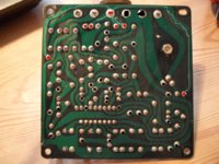
Attached is a pic of my PCB, it looks fine to me.
 

Attachments

  • TCI PCB top.JPG
    TCI PCB top.JPG
    84 KB · Views: 1,564
  • TCI PCB R&B.JPG
    TCI PCB R&B.JPG
    92.7 KB · Views: 749
There are two or three good threads about these if you understand electronics(i don't).
A little searching will turn those up. Reading the threads it seems a common complaint has been crapped solder joints. Resoldering has help several.
There was one(thread) that talked about changing the little black thing in the upper left iirc. I think sourcing the part was the biggest hurdle.
 
Thanks. I've spent a while online trying to figure it out. (I don't really understand electronics either but I'm trying to learn)

Based on the instructions below, the transistor you're talking about does look dubious, but I think it's difficult to properly test a component while still in the PCB and I don't want to mess with it unless I have to.

http://www.650rider.com/index.php?name=Forums&file=viewtopic&t=1015&postdays=0&postorder=asc&start=0

If someone can check the resistance on an ignition unit as in my post above, it would tell me if I'm on the right track.
 
You should be able to check the diode with it installed on the board. It is essentially a 1 way valve for elecrical flow. Power should be able to enter at B, and exit at C and E. but should not flow the other way. That's why the polarity matters. The meter, when doing this check, sends a small DC voltage throught the positive lead, in this case, your power should enter at B, and should be allowed to exit to C and E. The arrow in the diode diagram is always pointing the direction current should flow. If it comes the other way, it hits "the wall", the perpendicular line across the circuit.
 
Thanks for explaining that JD.

It flows from B to C and E as it should (reading of about 0.530).

And although it doesn't flow from C to B, it DOES flow from E to B (reading of 0.561) (and E to C if that's of any significance).

So does that mean it needs replacing?
 
Yes. Should not flow from B to E. It flows from E to C because the E side "wall" is torn down. Good troubleshooting. now you are off to Radio Shack, or whatever store you guys have for that stuff over there!
 
Thanks for explaining that JD.

It flows from B to C and E as it should (reading of about 0.530).

And although it doesn't flow from C to B, it DOES flow from E to B (reading of 0.561) (and E to C if that's of any significance).

So does that mean it needs replacing?

Your test of 74.5 ohms may be quite normal. All circuits have resistance and draw current flow. Your assumption that the resistance should be infinite is wrong.

You cannot test transistors or diodes while they are connected into a circuit board. This is because there are other components connected in parallel on the board. If you had a diagram of the board, with the values of the other components, it might be possible to do some testing. Without a diagram of the CB components, you're just shooting in the dark.
 
How hard would it be to just pull that thing off the board then? If I'm reading the PCB trace correctly, E is in your ground trace, and should have continuity with the ground wire. The trace for C goes straight to the orange and white wire. If C leaves the board, and E is the ground reference, and there is a diode in between as the illustration in the above referenced link shows, then the diode at E is bad. There is nowhere else for them to connect, except through the diode, which should be preventing it. The referenced procedure does not say anything about pulling it off the board first. That was the reason I came to the conclusion that the diode at E is bad. Take it off the board and test it again to make sure.
 
Last edited:
You say it ran before you re-wired it. That says to me that there's almost 100% certainty that you wiring is bad, not the ignition box, and that you have not been able to find the mistake in your wiring. Or you refuse to consider that there could be a mistake in the wiring! The boxes are pretty rugged.

That said, the best way to test the box is by substitution. You need a spare around anyway, so... If you're not an electronics guy, e.g. you tolerate people telling you how to test a transistor, you'd best stay out of there. You might as well be trying to fix a computer board.
 
+1 ^ In your other thread, I suggested some things to try, did you?

Posted via Mobile
 
Thanks for your advice.

JD. As you say "The referenced procedure does not say anything about pulling it off the board first", and it does test as bad, but I tend to agree with retired gentleman: probably the only way to test it properly is off the board. I'm reluctant to do this though because I would be surprised if this is the problem.

I would be the first to admit if I've made a mistake with the wiring, and I was sure I had made a mistake. As I've been reminded - it started when I bought it! (all be it for two minutes and poorly). However - I have checked it over a dozen times and can't find any mistakes - but maybe there is one.

Retiredgentleman: you say "Your test of 74.5 ohms may be quite normal", and it might be, but it means there is continuity between the live at the coil and ground. This might be quite normal, and I'm wrong to assume it's the cause of the problem, but after going through the whole system a few times, it's the main area I'm concerned about and one which could easily be verified. (and now that the transistor seems to test bad (based on the agreed test procedure), I feel right to be concerned about the ignition unit)

xjwmx - Attached is my wiring diagram. I've wired it the same as the diagram - PLEASE tell me if you can see a problem. I certainly don't refuse to consider I've made a mistake - I wish I had, it might be easier to solve. But only I can check for my mistakes, which I have been doing for over for a month and I can't find anything. If these boxes are so rugged, why would I need a spare? They are expensive now, especially as the ones available are used, so buying another one just to test mine by substitutuion seems excessive. If I knew there was supposed to be continuity between ground and the red wire / live input at the ignition unit, then I could rule out the Ignitor as the problem.

Yamaman: Thanks for your advice, I did all the tests you suggested and no luck. With a hot wire straight from the battery to the coil, there is still a voltage drop because this wire also goes from the coil +12 to the ignitor unit, which is leaking to ground (which may or may not be correct)

I'll have another look at it after work tonight - I'll get it sorted whatever I do!
 

Attachments

  • wiring.JPG
    wiring.JPG
    86 KB · Views: 5,182
Last edited:
ok, I guess the TCI is looking more suspect. goodluck, cheers

Posted via Mobile
 
Thanks Yamaman. It still might not be the problem. If it is faulty, I could have damaged it by something i did wrong when wiring up, or trying to start it for the first time. Who knows, I'll work it out.
 
Brett;

Have you taken out a spark plug (ground the body)and tried to view the spark in a darkened garage/shed, to confirm there is no spark at all, or a weak spark?

Have you measured the resistance of the pick-up coils, mounted on the alternator? They should be around 700 ohms each.

Your trouble shooting seems to involve a lot of assumptions and guessing, which just won't find the root problem. I don't think you have any reason to believe the TCI is defective.

You can't trouble shoot a TCI board properly unless you have a manufacturers circuit diagram, circuit description and an oscilloscope.

I agree with xjwmx, in that the problem occurred after the re-wiring, you should be looking at all the connectors/wires very carefully. Your wiring diagram looks to be fine.
 
If it ran before you rewired it your TCI is more than likely good. I know someone out there is going to disagree with me on this but I've never had to replace a TCI on any Yamaha! I've been at it at the dealer level since 1973. Double check your wiring and you will find your demon.
 
Retired gentleman.
"Have you taken out a spark plug (ground the body)and tried to view the spark in a darkened garage/shed, to confirm there is no spark at all, or a weak spark?"
Yes, two months ago and there was no spark. See the last post here: http://www.xs650.com/forum/showthread.php?p=192373#post192373

"Have you measured the resistance of the pick-up coils, mounted on the alternator?"
Yes, two months ago, and they measure about 730 each.

I also tested the coil at the time. 2.7 across the primaries and about 23 ohms across the plug leads with the 5ohm caps on.

I don't see where the assumptions and quessing come into it? I think I've done a pretty thorough and systematic job of troubleshooting. If I've made a mistake, I wish I could find it!

Today I checked everything again, with the same results as above and all the connections are good and the same as the diagram. (Out of interest, there is a 0.4 ohm resistance from the battery+ via 20amp fuse through the ignition switch, the 10 amp fuse and the kill switch to the coil/ignition unit)

A couple of extra things though:

With the spark plugs out and grounded, they spark once when I switch off the ignition or kill switch, even if I don't kick it over and just switch it on and off (the reason for the cough back through the carbs and exhaust I first noticed).

(With the key and kill switch on):
The battery (which is new and well charged) reads 12.46 volts, with the wires attached to the coil, I only get 11.33 volts between the red and ground but 1.34 volts between the orange and ground.
With the wires to the coil removed, I get 12.26 volts between red and ground and 0.62 volts between orange and ground. (this is all with or without the pickup attached).

Any ideas??
 
Last edited:
The B/W wire between the pick up to the ignitor? Thanks, I'll try it when I get back to the bike in the morning. I've already tried it with and without the pick up connected altogether and the results were the same.
 
On the 82 the TCI box has two black/white wires. One goes to the pickups, one goes to the sidestand relay.
The one that goes to the side stand relay gets grounded when the side stand is down and you put the bike in gear. This stops the engine. A safety thing.
You say you cut the wires of to 4 inches from the TCI box anddid some soldering. When you did this you might have reversed the two black white wires.
I might try swapping those two wires and see what happens.
Leo
 
Last edited:
Thanks Leo. There's only 6 wires on my TCI box , it didn't have the sidestand cutout. (as can just be seen from the photo of the TCI in my first post on this thread)
 
Back
Top