I can confirm he is still working on things and should be done soon. He's quite the visionary with this project, so thankfully I have more time than he needs :-D
-
Enjoy XS650.com? Consider making a donation to help support the site.
XS650.com receives a small share of sales from some links on this page, but direct donations have a much greater impact on keeping this site going.
You are using an out of date browser. It may not display this or other websites correctly.
You should upgrade or use an alternative browser.
You should upgrade or use an alternative browser.
Wannabriden's D Port Re-Port
- Thread starter BluzPlayer
- Start date
Reports of my demise are premature.
Apologies for not continuing the updates but work has continued. Delays during periods of researching, and testing materials, epoxies etc.
Bottom line is the head is complete and has been sent to Garrett. He should have it sometime tomorrow. The testing turned out great and the head looks great as well.
I will begin posting all the information and data as well as review the port design and try to answer any questions during the next week.
Good to be back
Here is a short clip with some pics..
Not what you are waiting for I know but I am trying to lay out the presentation before it is presented.
IF that made any sense,
There is a ton of data which has to be moved from one device to another and not in a friendly manner.
Very shortly I will begin presentingeverything.
So for the moment....
Not what you are waiting for I know but I am trying to lay out the presentation before it is presented.
IF that made any sense,
There is a ton of data which has to be moved from one device to another and not in a friendly manner.
Very shortly I will begin presentingeverything.
So for the moment....
For those that have been following as well as any others:
I think there should be a brief review.
We'll start with styles of porting.
When I first did this in my teens on small block heads I didn't have any real test equipment.
The biggest shop vac I could find and some string.
Combined with a basic understanding of fluid dynamics, it seemed to be enough.
Seat of the pants says it worked great.
I did several for others over the next couple of years.
Then into the Air Force and the rest of life.
Inspired by Jack's thread, once I decided to pursue this
I knew I wanted to be able to gather data at a higher level.
Not cheap even when you DIY, but it's been worth it.
The philosophy hasn't changed since the beginning..
"Do the best you can with what you got"
Style One
"One Size Fits All"
This is the style I utilized in my teens.
Make it go all it can go...
Style Two
"Tuned Port Engine Specific"
The port is design based on an engine's volumetrics.
Those specifications are what determine the volume of air required.
Using formulas from SAE or those derived from them will give the values to target.
Velocity is KING. I like the maximum before going into choke.
I'll discuss this point in the report further as we go.
This rebuild was Tuned Port Engine Specific.
Since the engine specs are required to go further I have provided them here..
Engine Specs - 700cc w/ Shell #1
Intake Valve
Length 4.105
Stem 0.3146" / 7.99mm
Head 1.614" / 41mm
Area = 1319 sq mm / 2.04 sq in
Exhaust Valve
Length 4.030"
Stem 0.3136" - 7.96mm
Head 1.378"- 35mm
Tulip Angle 23
Area = 961 sq mm / 1.49 sq in
Left
Port Runner Length 86mm / 3.38"
Port CC 74cc
Port CSA 1.16"
Right
Port Runner Length 87mm / 3.38
Port CC 75cc
Port CSA 1.15
77.5mm bore (700cc) 2.972"
74mm stroke 2.913"
130mm Rod 5.12"
Rod to Stroke Ratio of 1.756-1
Piston Speed
63 fps / 756 ips
700cc = 40.4 ci
Establishing Targets
The goal is to have all the targets confirmed with inter-related formulas.
Engine formulas are available in many places, including those that complete the calculations once the required parameters are entered.
One should always double check the values.
Always review any unexpected or out or norm findings.
Retest and Verify.
Target One
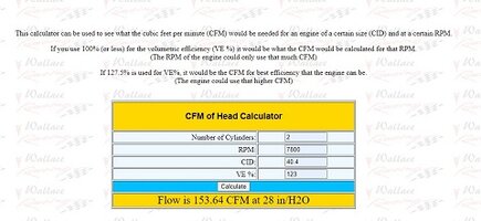
Required CFM
 CFM Head Calc.jpg")
So here we have a target CFM of 150 CFM for this 700cc w/ a Shell #1 cam.
Target Two
Optimum CSA
 CSA Max RPM Calc.jpg")
We can see that the optimum CSA should be 1.15 sq in.
Target Three
Maximum Port Velocity
There are numerous different standards related to determining a port choke point.
I spent quite some time studying this as well as speaking with other porters for a better understanding.
Ultimately I decided to use a simple determining factor.
When the pitot tube has a greater pressure than the atmosheric test pressure the port is poised for choke.
For these tests that pressure is 24" of water which equates to around 340 fps as a target.
Additionally the port should be as "equalized" as possible. Less variation is better.
I test the port at three different "depths" in mulitiple locations.
I labeled the depths on my charts as 20mm,40mm,60mm.
In reality those are incorrect, the accurate depths are as follows:
15mm - 8 test points

35mm - 7 test points

55mm - 7 test points

Total of 22 test points for Velocity
The targets identified with the previous information based on engine volumetrics:
CFM - 150
CSA - 1.15
Port Velocity - 340 fps
The closer to these values the better.
Consistency of measurement is PARAMOUNT!
Set the standards for your bench and stay within them.
Tighten the standard whenever possible.
What do these targets represent and how important are they?
CFM
A N/A engine is basically an air pump and the amount of air that can be moved through the motor is dependent upon the motor specifications.
Falling below this number chokes the motor. Too far above it will reduce port efficiency as well as shift the power curve.
Cammed timing events and power curves must be taken into consideration.
CSA
The CSA is sized to achieve the required flow.
Knowing this number eliminates guesswork, hit and misses...
Port Velocity
Port Velocity is by far the most important number here.
Next we look at problems and solutions.....
I think there should be a brief review.
We'll start with styles of porting.
When I first did this in my teens on small block heads I didn't have any real test equipment.
The biggest shop vac I could find and some string.
Combined with a basic understanding of fluid dynamics, it seemed to be enough.
Seat of the pants says it worked great.
I did several for others over the next couple of years.
Then into the Air Force and the rest of life.
Inspired by Jack's thread, once I decided to pursue this
I knew I wanted to be able to gather data at a higher level.
Not cheap even when you DIY, but it's been worth it.
The philosophy hasn't changed since the beginning..
"Do the best you can with what you got"
Style One
"One Size Fits All"
This is the style I utilized in my teens.
Make it go all it can go...
Style Two
"Tuned Port Engine Specific"
The port is design based on an engine's volumetrics.
Those specifications are what determine the volume of air required.
Using formulas from SAE or those derived from them will give the values to target.
Velocity is KING. I like the maximum before going into choke.
I'll discuss this point in the report further as we go.
This rebuild was Tuned Port Engine Specific.
Since the engine specs are required to go further I have provided them here..
Engine Specs - 700cc w/ Shell #1
Intake Valve
Length 4.105
Stem 0.3146" / 7.99mm
Head 1.614" / 41mm
Area = 1319 sq mm / 2.04 sq in
Exhaust Valve
Length 4.030"
Stem 0.3136" - 7.96mm
Head 1.378"- 35mm
Tulip Angle 23
Area = 961 sq mm / 1.49 sq in
Left
Port Runner Length 86mm / 3.38"
Port CC 74cc
Port CSA 1.16"
Right
Port Runner Length 87mm / 3.38
Port CC 75cc
Port CSA 1.15
77.5mm bore (700cc) 2.972"
74mm stroke 2.913"
130mm Rod 5.12"
Rod to Stroke Ratio of 1.756-1
Piston Speed
63 fps / 756 ips
700cc = 40.4 ci
Establishing Targets
The goal is to have all the targets confirmed with inter-related formulas.
Engine formulas are available in many places, including those that complete the calculations once the required parameters are entered.
One should always double check the values.
Always review any unexpected or out or norm findings.
Retest and Verify.
Target One
Required CFM
So here we have a target CFM of 150 CFM for this 700cc w/ a Shell #1 cam.
Target Two
Optimum CSA
We can see that the optimum CSA should be 1.15 sq in.
Target Three
Maximum Port Velocity
There are numerous different standards related to determining a port choke point.
I spent quite some time studying this as well as speaking with other porters for a better understanding.
Ultimately I decided to use a simple determining factor.
When the pitot tube has a greater pressure than the atmosheric test pressure the port is poised for choke.
For these tests that pressure is 24" of water which equates to around 340 fps as a target.
Additionally the port should be as "equalized" as possible. Less variation is better.
I test the port at three different "depths" in mulitiple locations.
I labeled the depths on my charts as 20mm,40mm,60mm.
In reality those are incorrect, the accurate depths are as follows:
15mm - 8 test points
35mm - 7 test points
55mm - 7 test points
Total of 22 test points for Velocity
The targets identified with the previous information based on engine volumetrics:
CFM - 150
CSA - 1.15
Port Velocity - 340 fps
The closer to these values the better.
Consistency of measurement is PARAMOUNT!
Set the standards for your bench and stay within them.
Tighten the standard whenever possible.
What do these targets represent and how important are they?
CFM
A N/A engine is basically an air pump and the amount of air that can be moved through the motor is dependent upon the motor specifications.
Falling below this number chokes the motor. Too far above it will reduce port efficiency as well as shift the power curve.
Cammed timing events and power curves must be taken into consideration.
CSA
The CSA is sized to achieve the required flow.
Knowing this number eliminates guesswork, hit and misses...
Port Velocity
Port Velocity is by far the most important number here.
Next we look at problems and solutions.....
Attachments


I'll get some detailed pics up soon :-D
A few before and after pics before we get started..
Left Intake Port
Should be obvious which are which...


Left Intake Port
Should be obvious which are which...
A few before and after pics before we get started..
Right Intake Port
Should be obvious which are which...


Right Intake Port
Should be obvious which are which...
A few before and after pics before we get started..
Left Exhaust Port
Should be obvious which are which...


Left Exhaust Port
Should be obvious which are which...
Last edited:
A few before and after pics before we get started..
Right Exhaust Port
Should be obvious which are which...


Right Exhaust Port
Should be obvious which are which...
Lastly Chambers and valves...
Left Side


Right Side....


Left Side
Right Side....
Hey Jay...I thought there would be a bit more work done on the combustion chamber, I have 2 heads both came with just about the same in the combustion chamber with all the edges smoothed right out.
Really a port repair for Garrett. I did a bunch of extra stuff.
I did smooth out the valve shrouding on the junk head provided by gggGary.
The testing from that showed little variation at these specs. with a .400 lift cam.
I was able to achieve the targets without having to do more than a slight smoothing of sharp edges,
so that is where I left it, other than a semi-polish.
Testing did show a potential for "vaning" the air flow to create more "swirl".
Something I may chase later.
Last edited:
Here are the CFM numbers for the head.
I tried to make the chart as easy to read as possible.
Left on the left and right on the right.
Measurements for lifts at .050 increments.
The full tenth lifts are highlighted in blue. I call them the "Top 4".
Total CFM is adding all 8 measurements once each.
RT means "Round Trip"; which adds all the CFM for each increment for a full valve lifting cycle.
Notice on the right side the "% Difference" which is the difference in percentage of increase from smaller to larger.
These percentages are for each lift increment. The CFM Difference shows how many CFM those percentages represent.
The red circle in the lower right shows the avg CFM/sq Inch across these 8 increments. Notice that number... 114 avg.
We'll talk about it soon.
The % Difference between the Total CFM for the 2 ports is .002%
The % Difference between the Top 4 RT CFM for the 2 ports is .004%
The % Difference between the All 8 RT CFM for the 2 ports is .005%
The ports arrive at from slightly different directions.
One is slightly better at the lower lifts and vice versa.
Still the numbers are incredibly tight.
I should remind everyone that the plus or minus on this bench is 1% to 2% depending on how far from the calibration points the air is measured. That should be considered within the margin of error.
BTW.. I took video of these tests and will post some snippets along with the corresponding data sheets sometime soon.
Remember that we have establishished a CFM target of 150 CFM
Here you go....
Last edited:
Similar threads
- Replies
- 15
- Views
- 973