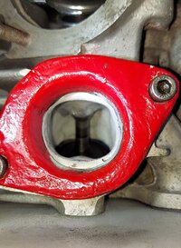
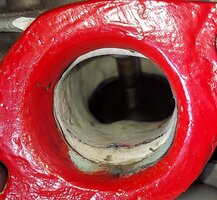
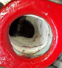
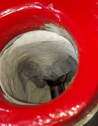
Wannabriden's D Port Re-Port

Gary I will flow test anyone's head that desires it.
The testing takes a bit of time, but not that long.
The compililation of data likewise.
I can do the full battery or choose which tests you want,
Obviously I can video whatever sections are desired.

The full battery:
CFMs (,05 increments)
Velocity Port Maps (@.20 & .40)
Valve DP (Dispersion around the valve)
Smoke testing (Video visual flow @ .1 increments)
Swirl testing (Video @ .1 increments)
Flowball Testing (Video port activity)

Addtionally I can physically map the port, including runner length and volume.
The report would include all relevant information regarding CSA, Coefficient of Discharge (efficiency), etc.

Since you stepped up and provided me with the junk head which has been a HUGE benefit to my testing;
I will gladly provide all the above or whatever parts are of interest to you for free.
That is no porting. Just the testing. Just a way of me being able to say thanks for helping me out with this endeaver.
Just send me a message when you get ready.

Should anyone else be interested, they can message me and I am sure we can work something out.
I am not trying make bank here, my bills are paid and I am retired.
Stock heads, performance heads, porting work..
Not everyone wants all the bells and whistles, but something we all want is a head that works well.
Check guides, valves, modified (Lilli) guides.
Just be sure you don't send me a cracked head. Unless it is an obvious crack I won't see it.
I have no way of testing for cracks in alum at the moment. Don't want the work to be wasted.
I do have some testing of basic mods (pocket porting) for stock heads coming in a seperate thread soon.
 
Might be interesting to flow test a Bob Bertaut head??? ;^)
If that head was ported by Bob you have something rare indeed. He once told me to concentrate on the exhaust port and for every 100 lift the flow should double and he was right. The first head I ported did just that on the exhaust and I did it all by using my fingers using 80 grit, 120 grit ,Emory cloth, AND BLISTERS. Exhaust poting on the XS head is very challenging because no two ports are the same, one is ideal, and the other lacking material or butchered from the factory.
 
If that head was ported by Bob you have something rare indeed. He once told me to concentrate on the exhaust port and for every 100 lift the flow should double and he was right. The first head I ported did just that on the exhaust and I did it all by using my fingers using 80 grit, 120 grit ,Emory cloth, AND BLISTERS. Exhaust poting on the XS head is very challenging because no two ports are the same, one is ideal, and the other lacking material or butchered from the factory.
I posted what I think I know here
https://www.xs650.com/threads/ggggarys-latest-xs-project-madness.28289/post-801421
some port pics there don't know if they show anything.
Again would be interesting to have someone that knows look at it and mebby con Bluz into flow testing it.
 
That must have been a nasty bug, good that you are up and about again.
I find you videos very useful and always learn something, thank you.

With regard to shortening the valve guides. I have been struggling a bit to work out if Jack shortened both the exhaust and inlet valves the same.
From the photos in his thread the exhaust is shortened as he described but the inlets look like they are shaped like the Lillie replica guides.
What is your understanding of the modification he did to the inlet valve guide.
If using stock guides, I take the exhaust length down to the intake. Looking at the bottom inside of the exhaust guide, you'll see a step that serves no purpose take it down to that step. When I purchased K/W guides decades ago both guides were the same length, they may not be that way now since
they are duplicates of Lillies mods. On the intake, I just profiled them in place while porting. Are you comfortable porting the exhaust? They can be a
challenge, the exhaust port responds best with a tulip valve with a thick margin to allow a radius to the margin for a smoother flow transition that yields more flow and of course, eliminating that big bulging guide in the air stream. These mods alone contribute to big gains along with removing casting flaws.
 
LOL..
No conning necessary.
One of the reasons I took on Garretts project was II initially thought it was a chance to see some of Jacks design,
Obviously it was just a copy of that. I think it would be enlightning to test that head and document it as you wish.
I will send you all the results and you can post what you wish or I can t post it in a thread.
I'm pretty easygoing. Besides, I already owe you, That junk head has been gold to me.
 
I posted what I think I know here
https://www.xs650.com/threads/ggggarys-latest-xs-project-madness.28289/post-801421
some port pics there don't know if they show anything.
Again would be interesting to have someone that knows look at it and mebby con Bluz into flow testing it.
If Bob ported that head, he was having a bad day because he had a particular way of porting the exhaust while over the years incorporating a
D shape to the exhaust. Unfortunately, I no longer have those photos he sent me to show you what he did but I will check.
 
@BluzPlayer

Quote "However, recent discussions in the thread regarding information from Access Norton have veered me off course.
Only the initial attempt at meshing some of those ideas with my present studies..... But I must say the data looks great."
(My quoting function doesn't seem to work.)

As mentioned the Commando head (ports and chambers) are of a distinctively different and of a vastly superior design that allows or even invites one to conduct such modifications.
On a xs I estimate such an undertaking rather difficult without access to a full blown machine shop (mill, lathe, Tig, etc) with, in comparison to the gains on a commando head or let's say A65, diminishing results given the nature of the cam grinds usually chosen for Xs'

Kind Greetz

Christian

Ps: yes I mostly work on St/XT/TT heads, of which I posted at times on the old flat track.com racing forum together with some other guys (I think, Millard, Lineweaver etc), but also as well on most of the Classic Brit/Italian top ends as well as classic japanese 4valvers and some car cylinder heads (ford cossies, pintos, and Blmc A/B)
 
Last edited:
@BluzPlayer

Quote "However, recent discussions in the thread regarding information from Access Norton have veered me off course.
Only the initial attempt at meshing some of those ideas with my present studies..... But I must say the data looks great."
(My quoting function doesn't seem to work.)

As mentioned the Commando head (ports and chambers) are of a distinctively different and of a vastly superior design that allows or even invites one to conduct such modifications.
On a xs I estimate such an undertaking rather difficult without access to a full blown machine shop (mill, lathe, Tig, etc) with, in comparison to the gains on a commando head or let's say A65, diminishing results given the nature of the cam grinds usually chosen for Xs'

Kind Greetz

Christian

Ps: yes I mostly work on St/XT/TT heads, of which I posted at times on the old flat track.com racing forum together with some other guys (I think, Millard, Lineweaver etc), but also as well on most of the Classic Brit/Italian top ends as well as classic japanese 4valvers and some car cylinder heads (ford cossies, pintos, and Blmc A/B)
Is Jim Comstock the one doing the Norton head work? He's got a Norton 850 head of mine for rebuild work, (17 months and counting... :cautious:)
 
@gggGary

Hi Gary,

To my knowledge Comstock is having, or had (according yo some posts a while back) , a hefty backlog of work, so I wouldn't know.
Originally the xr750 style commando ports were the idea of Jim Schmidt, so I assume he does /conducts the downdraft Harley XR Style ports.
As mentioned, the overall idea/approach is imho (as i did years ago on a race DBD34) to raise the port roof in some parts, where not possible, to raise the roof, gain necessary port area in widening the port, and thus have a smoother less turbulent SSR and a more efficient port
I purposely explain in such Briefness as the explanation gets otherwise outta hand, besides the narley idea is schmidties baby.
Basically I assume that the JS Narley ports are highly similar to the B50 "full race heads" of Stan Millard or some of my Sr Frankenstein heads, higher, more direct, partially oval, etc. and destined to be used with high lift cams that support big valves and suitable cams.

Kind Greetz
Christian
 
@BluzPlayer

Quote "However, recent discussions in the thread regarding information from Access Norton have veered me off course.
Only the initial attempt at meshing some of those ideas with my present studies..... But I must say the data looks great."
(My quoting function doesn't seem to work.)

As mentioned the Commando head (ports and chambers) are of a distinctively different and of a vastly superior design that allows or even invites one to conduct such modifications.
On a xs I estimate such an undertaking rather difficult without access to a full blown machine shop (mill, lathe, Tig, etc) with, in comparison to the gains on a commando head or let's say A65, diminishing results given the nature of the cam grinds usually chosen for Xs'

Kind Greetz

Christian

Ps: yes I mostly work on St/XT/TT heads, of which I posted at times on the old flat track.com racing forum together with some other guys (I think, Millard, Lineweaver etc), but also as well on most of the Classic Brit/Italian top ends as well as classic japanese 4valvers and some car cylinder heads (ford cossies, pintos, and Blmc A/B)
If my memory is correct on the XS you can only raise the roof 3mm and are limited to opening the sides too. Years ago Hanson Racing out of Californa
took the XS exhaust port and duplicated the resigned racing E/P that featured the straightening it out for better flow performance. Now mind you Hanson Racing is no backyard speed shop known for bench racing and their efforts were rewarded with no gains over a stock port fully ported.
Although the Narley ports look impression on the bench and in the art form, sometimes it's just best to work with what we have cuz just the cost and
time invested isn't worth the hassle of lost gains in the end.
 
Good morning guys.
I am as always greatful for the vast wealth of information you share.
It is amazing to me that we have such a wealth of knowledge here in these pages.
Let me say that I am not actually approaching the Narley head directly as you might expect.
I was simply intrigued by the basic philosophy with the constriction being at the mouth of the port,
then widening before constricting again before the bowl. This is in the most basic way the same as a stock head.
In the stock head the round port swells open with the bulge near the guide maximizing about 45mm in before reducing again before the bowl.
I have found the templates for the Narley and it does this similarly athough one of the main ideas they used was a reduced height as related to the width of the port. In the slices shown in the template (every 15mm) this can be seen. They aslo arch the roof on the center 2 "slices" in effect raising it, but not by a large degree before returning to a basic oval shape for the last contriction at the bowl.
As for having the space required.....
Using basic ratio-metrics I have adjust the dimensions of the Narley port for scale with the xs650.
Clearly the roof height is not an issue as the xs650 is taller throughout. That will be addressed mainly by raising the floor.
As for the width dimensions, it remains to be seen (which is why I got the junk head) if there is enough width available.
Preliminary measurements taken from within the port as well as using the molds I took earlier (much easier and accurate) seem to show the possibility is there. There is really only one area that I see as a major concern, That would be about 20mm inside the opening where the stock head is around 35mm.
The Narley template calls for39. So that would require 2mm per side. Obviously to follow a concept or an idea does not require duplication to exacting standards. The idea being that the height becomes more "squished" by 2mm as the width increases greatly from the opening (32.5 mm).
I should note the dimensions I am using are those that would apply to the xs650 after conversion.

I have only to this point used the Oval shape at the opening and reshaped the beginning of the port to accommodate the change.
My flow numbers are similar to what I had before the change. The velocity numbers had a very substantial, very significant increase.
Even more so the velocities were not only higher (approaching maximun) but they were more consistent throughout the port.
I will be presenting all this data of course. I am hoping to complete the full battery of testing today for a baseline to the changes as I begin following this concept further down the port. There are 4 main areas to address:

The Opening (Oval shaped and dimensioned) which is complete.

15 mm in which is the area of potential width issues I mentioned above.

30mm in which is the point of the largest swell which coincidently coincides with the swollen area already existing on the stock head. This will actually require a reduction in width along with some reshaping.

45mm which is the final oval shape before the bowl.

Due to the difference in port lengths I am thinking I will be adjusting those "depth in the port" numbers to suit the xs650.
They basicall just quartered the runner length from the valve as they set up these various "zones".
I will most likely start there. That would mean evry 20mm instead of every 15mm.

There is no guarantees that this design will be effective on the xs650. Obviously the ports are different to begin with,
The port of the xs is flatter I believe for one thing. Regardless the basic concepts seem valid to me (especially since they somewhat mirror the ideals and goals outlined by Vizard when describing an "ideal" port) and I think can prove effective.
I see no need for milling or any great amount of work such as was required on the Norton head.
This is because the xs port is caverness as well as the conversion of the Narley dimensions to work within the existing port opening.
I might add that after scaling the oval constriction at the mouth, those numbers just happen to translate into the optimum CSA as computed in one of the videos (Porting 101 ???) posted earlier in the thread. As always I believe in setting targets that are dictated by the specific engine specifications.
That this target matched up with the scaled Oval opening is exactly what I am always seeking. If that number had been off any significant amount it would have abeen a huge red flag, Instead it was a bullseye and the testing with regards to flow velocity indicate the same.
I feel that it has already shown to be a success based upon the increased velocities I attained with the first iteration simply using the scaled oval on a previous port design I know is not yet optimal. As always the tesing will dictate, but it is the sharing of ideas and concepts that make things like this happen.
I will be following this up and providing the data as I progress. Takes me a day or two to compile some of it and prepare it to be presented.
But it is possible I could have some of the velocity stuff later this evening.
Time to go play with "Lovelace".
Have a great day!

Edit..
See the port stacked slices attaches for reference
* I converted the distances from the opening (what they call end) and they measured from the valve.
Hope it doesn't confuse.
Also pic of the Oval on the bench


Narley in port stack.jpg
20230714_173136.jpg
 
Last edited:
You do realize JS Motorsports has 3 versions of the Narley port? One for the street(CCs) middle(S&S) and the layout you provide for all out racing. Due to the bowl enlargements,the power band will change dramatically, sorta like adding more cam duration. You need to read Mark Parkers testimony of the before and after effects of the Narley port. He has a YT/V I believe,Mark Parker BSA rephased, he has a few vids, best sounding BSA on the planet
 
Last edited:
No Jack. I was unaware.
Indeed I had no idea of this concept at all prior to you pointing the way.
Again you offer up more nuggets.
I feel confident that the port design can be tuned for a hot street engine but unfortunately as we all know confidence doesn't always provide the end result. I will absolutely researchbwhat I can find from this new lead you have provided. There is nothing set in stone for me and I am able alter and or modify any ideas as required.
The port I just modified with the Oval opening/ roof addtion was already a well performing head with a few known and addressable issues.
It is already a higher performing head if I were to stop now. So this inspiration/information has already paid me benefits. It does not yet have the swells of width as presented in the Narley but instead utilizes something more equivalent to your D Port with straightened side walls.
Hopefully you can tell from the poor pics I'm attaching. Keep in mind these are clay surfaces (which make molding and changing shapes much easier) so the finish reflects that.
I have yet to massage them as this is just testing preliminary data.

Oddly where the D Port straightened the wall (in effect reducing CSA), this is done more so by squishing the height and oval-shaping the side walls in this Narley concept. Similar idea but applied differently. No telling without the exploration which direction I will ultimately end up going. I find the concept interesting regardless and look forward to seeing how they may or may not be applied here. As always the more information available, the more informed decision-making one can accomplish.
Thanks again for providing me with addtional avenues of exploration. There always seems to be nuggetts of value to be found and explored.

20230715_120200.jpg

20230715_120207.jpg

20230715_120213.jpg
 
Last edited:
Some velocity mapping showing the comparison of the stock head to this latest Oval 1 attempt at .20 lift.
Remember that at .20 and below (on this engine) the VALVE is in control. The port influence is reduced.

The 0mm is just at the mouth, where the red "bell" meets the head.
Not truly relevant and the numbers skew because this it where the venturi begins.
However the bell is the same for each and oriented the same, so it is a direct comparison.
The pressure pattern of the Oval1 design being more optimum.
Note that the Max velocity of the stock head is lower than the Min velocity of the Oval 1.
Stock Oval Comps 0mm .20.jpg


The same comparison at 20mm in the port.
Here we can see the velocities of both heads are greatest toward the floor of the port.
With the Oval 1 however the velocities rise higher within the port.
Note that similar to before the Max velocity of the stock port just equals the highest of the 2 Min velocities in the Oval 1.
Stock Oval Comps 20mm .20.jpg


At 40mm inside the port we see the following.
Both ports share the same velocity pattern.
Note that once again the the Max velocity of the stock head is below the Min velocity of the Oval 1.
Stock Oval Comps 40mm .20.jpg


Finally at .60 we find that the port velocities are equal.
Note the dispersion of the velocity pattern between the two.
It's not just the numbers. It's what is inside the numbers.

Stock Oval Comps 60mm .20.jpg


Conclusion...
This port design (particulary at this point) has been tuned toward higher lift,
The simple reality is that a port design's influence is limited at this low lift which is more influenced by Valve, Valve Seat, and Throat.
So such small gains are what should be expected. Huge numbers here would indicate an issue.
Lets get to the opened Valve...
 
Last edited:
Here are the comparisons at .40 lift (Maximmum lift availble with this Shell #1).
This is where the port has the greatest control, and the results should reflect that.

Again I will post the 0mm just for comparison.
VERY similar pattern as we saw at .20 which is expected.
We can now start to see the difference in velocities start to stand out. It is no longer even close.
Note that the Max velocity of the stock head is lower than the Min velocity of the Oval 1.


Stock Oval 0mm .40.jpg


20mm into the port...
We see the velocities sink toward the floor somewhat compared to .20lift we just discussed.
Note that the Max velocity of the stock head is lower than the Min velocity of the Oval 1.

Stock Oval 20mm .40.jpg


40mm inside the port...
Once again we see the same velocity pattern just as we saw at .20 lift.
Here where the port has taken control we see a HUGE difference in air speeds.
Note that once again the the Max velocity of the stock head is below the Min velocity of the Oval 1.
Far Below.


Stock Oval 40mm .40.jpg


Finally at 60mm just before the bowl.
We can see similar results and patterns to those we saw at .20 lift.
This part of the port is a bit larger, thus slowing the velocities.
Purpose is to build pressure before reaching the throat which is the point of greatest velocity (not measured here).
I discussed that concept in one of the porting videos earlier in the thread.
We can see looking at the Oval 1 diagram that there is work to be done on the roof area.
Just one of the very many things that can be gleaned from these charts.
Note that once again the the Max velocity of the stock head is below the Min velocity of the Oval 1.


Stock Oval 60mm .40.jpg


Conclusion...
Once the valve has opened enough for the port shape to take control we can see the real differences.
At .20 lift the difference between the 2 designs were not nearly as apparent. Gains were there.
They were modest and yet still significant, but not in your face as we see here at .40 lift.
There is more to come....
 
Just a comparison of the Oval port at .20 lift to itself at .40 lift.
Not much to see really. Obviously with the greater opening of the valve allowing the movement of more air, the velocities increase as well.
Similar patterns are observed, although it is worth noting how the faster air prefers the floor.
More noteworthy than the perhaps obvious previous observation is that the gains remain constant at 32% (+2-1 variation) throughout.

Oval Comp 0mm.jpg


Oval Comp 20mm.jpg


Oval Comp 40mm.jpg


Oval Comp 60mm.jpg
 
What are the dimensions of the oval opening and are how you calculating these velocities without an actual port to base them off? It seems you've
applied a lot of clay within the port for this particular experiment, so my question is, how would expect the average enthusiast or hobbyist to recreate
this extreme reconstruction makeover on the intake port? There's no way I would ever attempt putting epoxy in the bowl or on the side walls for fear of breaking loose. Are you planning on welding all this up? My thoughts of attempting this oval porting years ago were to raise the floor 6mm, oval opening
width 38 to 40mm with a height of 28mm then gradually raised the roof to form the Narley Eyebrow effect to the bowl.
 
Last edited:
Back
Top