Wannabriden's D Port Re-Port

Lastly without explanations I will include comparisons of the stock head, the Mod 12, and the Oval 1.
Brief description of each..

Stock- no description necessary.
Mod 12 - The Vaned head mentioned and shown previously.
Oval 1- This is the Mod 12 with the modification of the opening by adding an Oval shape.
That was somewhat blended but otherwise no changes. So basically the variations between
the Mod 12 and the Oval 1 are a result of modifying the opening from the "Vane" to the "Oval".

0mm @ .20 lift

Trio Comp 0mm .20.jpg


20mm @ .20 lift

Trio Comp 20mm .20.jpg


40mm @ .20 lift

Trio Comp 40mm .20.jpg


60mm @ .20 lift
Trio Comp 60mm .20.jpg


The Mod 12 is a high flowing head.
It flows 154 CFMs at .40 lift.
It has some known adressable issues that I am aware of, but overall flows very well, already outperforming Garrtt's D Port baseline.

Now the same comparisons at .40.

0mm @ .40

Trio Comp 0mm .40.jpg


20mm @ .40

Trio Comp 20mm .40.jpg


40mm @ .40

Trio Comp 40mm .40.jpg


60mm @ .40

Trio Comp 60mm .40.jpg


We can that there is an issue in the area around 40mm within the port as that is the only point at which the MOD 12 outperformed the Oval 1.
So between the 20mm zone and the 40mm zone we should be looking should we decide it is something needing to be addressed.
As the difference between the averages is only 4 CFM that may not be necessary.
Of course there could be specific points within the area we will want to address.
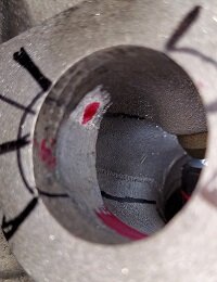
Lastly there is the velocity pattern shown at 60mm demonstrates the vaning created by the opening of the MOD 12 compared to the Oval1 design.
 
Last edited:
Good questions Jack.
The velocities are calculated from the differential pressure of the pitot tube as measured with my digital DP meter.
The meter itself provides calculation which is what I was using as a comparison omly as I had yet to verify it's calibration.
The calibration was "verified" by using accepted formulas some of which provide the calculations for you. Simply enter the DP..
Using 2 of these as well as the built in function within my meter showed the results to be very close with my meter being the greatest variance of the 3. There is a program call Pipe Max which is also quite useful in helping with calculations.
The meter provides for a calibration adjustment which brings all three in line. The only "critical" aspect of the velocity measurement has to do with concerns regarding choke which in itself has many different ways of being calculated. It is for the choke numbers that I have any concern whatsoever in the calibration of the pitot tube. For port mapping itself the actual velocities are inconsequential as long as the procedures and testing are repeatable. It is comparative. The added step of verification involved the averaging across a ports CSA. Then measuring runner length and port volume (CCs) along with the CSA and CFMs flowed at a determined depression (28" water) you are able to calculate the ports average velocity. The numbers should be at least somewhat aligned. I am confident that for what I am doing here the calibration is close enough.
I included an example of one of those formulas below for the Oval 1 Head at .40. It flows 154 CFM at that lift.
The formula shows 293.62 FPS... My measurements come in at 291.
Always, Always, Always use information which can be cross checked for verification whenever at all possible.

FPS CSA Formula.jpg

Oval 1 60mm .40 .jpg


The Oval opening at the moment measures 32.3 w by 25.3 h which is what the ratio-metrics determined.
Of course the determining factor in sizing the opening and thus the rest of the port was the existing opening.
That equates to about a 1.26 CSA which is in line with the engine specific calculations way back in the Porting 101 thread.
I centered the Oval giving room for the roof raises further within the port simultaneously raising the floor which I consider an absolute.

Yes there is indeed a good bit of clay involved in that rendition at the moment.
Clay is used because of the ease of changing the port design again and again, not to mention the costs saving over using epoxy.
Less work and effort to reshape and less money. That's called a win win.
It is in places that it will not be once a port is actually designed as I had already opened the bowl significantly just to begin.
Not an issue as I could obviously add back clay to regain the shape. Which I ultimately did.
I do not exect any buildup in the bowl with the final design as I will not be opening it as I did on this particular port.
There may be some blending involved
As for the side walls.. It will depend on the final design how I approach it.
I most certainly have some of the same concerns you mention regarding epoxy, however some of the top porters do use it in that location without issue or at least those issues aren't brought to light if they do exist.
The copy of your head that Garrett sent me was not welded on the side walls as you did on your D Port.
The result was the beginning of delamination which I spotlighted in a video earlier.
However the floor had absolutely zero issues and could not have been bonded better.
That was without any anchorage that you suggested in your D Port thread. The thickness was just over 3mm.
I do like how your technique doubled as a guide for floor height and webbing ties it together though and it may be used.
It is my opinion the sidewall delamination was an issue with the application process.
There is no reason to believe that epoxy won't stick to the wall any less than it sticks to the floor.
The materials are the same. The pressures are no greater. However the fact is I have an example of a failed attempt on my bench.
So yes I share the concerns. I have done some testing in anticipation of this problem and have more to do,
For the moment I have no definitive answer.
The roof is no different than the floor with less velocity so I see no issues there.
It really just comes down to preparation and careful application. The most critical part of the entire process.

I do not expect the average hobbyist to recreate this perhaps, although it should be somewhat less difficult than the D Port.
There is no milling requirement and the epoxy/welding shouldn't be any more difficult.
I do intend on having a thread for some pocket porting and demonstrating what works and how well it works for those less inclined.
Many on the site have already performed port clean ups etc, So that may be of some interest when I broach it.
 
Last edited:
My thoughts of attempting this oval porting years ago were to raise the floor 6mm, oval opening
width 38 to 40mm with a height of 28mm then gradually raised the roof to form the Narley Eyebrow effect to the bowl.
I would be curious as to how you arrived at your target numbers.....
 
I would be curious as to how you arrived at your target numbers.....
The Narley opening is 41.5 x 28mm for the racing mod and as stated, there are three levels with all having the same floor mods but the opening,roof and bowls mods are targetted for street use with higher velocity gains at lower RPMs . My plan was to start at around 36mm and work outwards till gains
diminished then reweld the side's backup to regain those losses,just a dream of mine.

PS..... there is no milling needed on D porting, it's all done by hand eliminating that step. It's no more difficult than what you're doing
 
Last edited:
Ok I see.
I scaled the templates so the width (the larger dimension) at the opening (what they call end) fit inside the stock opening. That scaled size just happened to coincide with the target CSA calculated for this engines parameters. So it worked out really well. A properly sized CSA is one of the most important aspects for well tuned efficient port. Based on the percentage of growth for each of the 2 inside templates, it appears they are doable without great modifications as well; although there is the one spot that needs a couple of mm on each side widened. Thankfully with the junk head I have no concerns about opening it up and seeing if there is room available. The parameters of the templates are not set in stone and can be adjusted as necessary. There are other "target" points as well that I will get to eventually.

I stand corrected on the milling requirement.
I thought I remembered you mentioning that you milled the head in your thread. The head on my bench was definitely milled. Certainly the opening could be done by hand although keeping that line straight and slope correct could be challenging. I would have to agree that the difficulty factor in these types of port modifications would be similar.
 
Last edited:
How did you scale the templates? Or did you buy his CD
Hey Jack,
No I did not buy the cd.
Originally I printed the template stack that I attached full size. Then I transferred it to graph paper. Using the 28mm known height of the Narley, I calculated the width. Then utilizing the width of the stock port opening I was able to calculate the height for the xs 650 head. Once I had that information I calculated the remaining measurements. I then measured my port mold to see how possible the meshing of ideas might be.
After the initial test showed so much promise; I used some software to print the template stack to the new actual size. I printed it 4 times on the sheet.
Now I can cut them out individually and transfer them to plastic (thin acetone?) to use in the port.
I am also going to create roof line and floor guides as well.
Of course they are simply templates to be used as a basic guide and will need modification as necessary.

You can have what I have Jack.
There is no real cost to me and I wouldn't even have been aware of this concept without you sharing.
I can email you the correct sized template stack or cut them and send it to you in a letter.
Just message me with your info.
I couldn't accept anything for them.
I would look forward to your discoveries and discussion on the concept.
 
Last edited:
We have discussed how it is importatnt to use several method of testing to see how well a head performs.
Just above I shared some examples of velocity mapping which is some of the very most important testing done.
In those examples one can see that not only does the Oval 1 port obviously outperform the stock head but the Mod 12 as well.
It is far more important for a port to flow high velocity than high cfm.
There are many people that only think of cfm and it is often a misleading figure.
In this example we can see the comparison in CFM flow between the Mod 12 and the Oval 1.
Remember the Oval 1 is the Mod 12 modified by changing from the Vaned opening to the Oval.
The reasons the Mod 12 was chosen to modify despite known issues?

The Mod 12 was a good performing head overall with some low lift deficiencies as well as a poor velocity dispersion at the highest lift.
It was the latest version ready to modify that I had completed all the baseline tesing on.
Therefore it makes identifying changes (good or bad) caused by the Oval port modification much easier.

In the attached Comparison Graph we can see that the Mod 12 still flows more CFMs than the Oval.
In both Total CFM and the more accurate Total Round Trip CFM the increase is 1.4 %.
Not a lot, still it IS an increase.
However when compared with the increased velocities shown in the graphs above it appears far more meager.
We will compare the data excepting the 0mm data (shown for comparison only) which is not within the port and less relavent.
Totaling the avg FPS for each head at the same three depths within the port gives us the following:

Mod 12 - 849 fps
Oval 1 - 946fps
The Oval 1 port had an average velocity 11 % higher.

So here (with the Mod 12) we have a head that flows 1.4% higher CFM and 11% less velocity
Just an example of why I do mutiple forms of testing as well as an example of why CFMs are not the numbers one should be looking at.
Always have targets.... determine your targets BEFORE starting to port.
Targets should always be derived from the specifications/parameters of the motor for optimum results.


Mod Oval CFM Comp.jpg
 
The Valve Differential Pressure showing dispersion.
Not much change, with the Oval 1 head flowing slightly better on both the sides as well as the long side splits (lst/inside, lst/plug) while sacrificing a couple of CFM at the short side turn as well as the long side turn.

aMod 12 All 8 Total VDP.jpg

aOval 1 All 8 Total VDP.jpg
 
Last edited:
I've completed the testing on Oval 1.
The test results were somewhat boring perhaps (especially since it is not a finished head) but I believe they illustrated a few examples that showcased why the various types of testing are important as well as pointing out to identify potential problem areas that should be addressed or at least further investigated.

As a result I have once again removed all the clay and preparing for adaptation to the Narley Concept attempt. I have scaled the templates and have transferred them to card stock.
The card stock seems to work better than the thin plastic (acetate?) sheet I originally tried.

I've done an initial "fitting" and it seems to be very possible. Perhaps the biggest concern being the first "eyebrow" inside the opening clearancing the oil passage on the inside wall after widening.
I am going to Arkansas for a couple of days, so it will be Thursday night before I can actually open it up and see. Then I will mold and test it on the port that has not been opened up in the bowl area. In other wirds I will be applying the modification to a stock port.

Attached pic of templates below...

20230718_203706.jpg
 
Offer still stands Rick - if you can get me a 3d model, i'll 3d print them for you.

One thing that might be nice to have, is a model of the combustion chamber & intake port. 2 pieces that would slip in together when the shape of the porting is correct, like a go/no-go gauge. Or it could be simply 2 pieces you can use independently.

I'm not a modeler, but if you can find a way to get the data to me, i'll make you copies to test out ;)
 
Put a pin in that 3d idea Garrett.
I have a few ideas so maybe.

Well I found the oil passage (intentionally)...
Had to identify it's closest point as well as be able to calculate wall thickness.
This pic is on the already opened up port.

20230722_132137.jpg


Of the four "zones" (15mm, 30mm, 45mm from valve and the end or opening) there are only two that may be problematic.
Each of the two "ends" (15mm and End) fit without any grinding required. The floor area will need to be raised as indicated.
The ceiling will need addressed as well at the end or opening creating the "Oval".
See the pics for reference:

20230722_220851.jpg
20230722_221409.jpg


Of the remaining two it is the 45mm from the valve that creates the biggest issue because of the oil passage along the inside wall as seen above.
The first thing I did was mark the template to the opening and then carry those "guide" lines into the port itself.
I also set the depth inside the port using a red ink. This clearly bracketed the exact location for grinding on each wall.

20230723_193547.jpg
20230723_193638.jpg


Once the grinding areas had been established I subtracted the stock port width measurement from the template measurement.
I then split the difference to tell me how much to grind from each side. Using the untouched stock port's outside wall as a reference:
I ground the inside wall slowly until I was just short of the calculated measurement.
You can see the red dot in the pic indicating the spot where the oil passage was closest.

20230723_193627.jpg


I then proceeded grinding the ouside wall until I was just under the template measurement.
Once that was accomplished I slowly continued grinding the two areas until the template was a fit.

20230723_205155.jpg


The ends look cut off as they are deeper within the wall than the opening.
You can see the edges fit correctly in the two pics below.
I will also point out that the clay on the floor measures 4.13mm which is near our target.
The floor will extend across the bottom between the two lowest black lines.

20230723_205159.jpg
20230723_205205.jpg


I am also including pics of each side after the INITIAL fitment grinding without the template in place...

20230723_205314.jpg
20230723_205321.jpg


The other center zone (30mm from valve) is now marked and ready to grind and then blend.
The template is slightly wider but the stock area is wider as well and there are no major obstacles to be concerned with.
20230723_205608.jpg
20230723_205615.jpg


Grinding this area is the last major surgery.
Then I will blend the zones and mold the port followed by testing to determine if it was worth the effort.
More to come....
 

Attachments

  • 20230723_193627.jpg
    20230723_193627.jpg
    48.1 KB · Views: 43
OK.
The other "inside" zone (30mm from valve) has been fit to the template.
Same procedure as outlined above for the 45mm from valve template.
After grinding the sides to accomodate the wider "eyebrow" of the template;
there will be a hump between the two locations. This is blended from the 45mm zone to the wider 30mm zone.
Be careful not to get deeper in either zone.
Also keep the blending within the marked area designated by the two black lines running inside the port on each side.

A pic of the 30mm template in place dead on.
Notice the floor gap which still measures 4.13mm with my feeler guage.
Obviously a raised floor is a given with any design.
That the templates provide a siimilar number that we have targeted from the beginning is promising.

20230724_173124.jpg


Pics of each edge of the template as located in the port..

20230724_173130.jpg
20230724_173139.jpg


Pics of both side walls without the template in place after the initial rough blending.

20230724_173311.jpg
20230724_173322.jpg


The next steps will be to modify the guide boss and install the shortened guide.
Then I will prep and mold the floor (still using clay).
Once the clay has cured (next day) I will start preliminary testing to guage the potential of this concept in this head.
At least as sized and executed my me for this test.
After I have those results I will mold the roofline and restest it again.
The testing results will at that point determine how I decide to go forward.
Plenty more to come....
 
Perhaps Skull the deleter struck again ???????
???? Merry Christmas Skull.
I missed a lot of the testing while on a road trip then this whole thread just fell off my plate and got lost.
I PM'd bluz also. no response yet, I'll give it a while, I (probably) have his address somewhere.
 
Hey guys, Rick's still working on things, just had a busy year end!

Things are looking better and better with every update that he texts me, but I'll let him explain things here as he has a far better way of doing it than I can ever hope for ;)
 
Back
Top