1981 XS650 SH charging issues on newly acquired bike

81 SH Rider

XS650 Member
Messages
5
Reaction score
1
Points
3
Location
Pacific Northwest
Hello everyone! Thank you all so much for the great information I have found on your site. A special thanks to 650Skull for leading me here. Recently got this 81 XS650 SH knowing it has some maintenance issues, but did know it started, ran and idled ok.... but on battery only till I rode it home, barely. Has a new battery, fuses has been changed to blade automotive. I keep a battery tender on it so it can start, run and I can do tests. After kick starting, the headlight is operating and after warm up, the headlight will just slightly brighten with some revs. At 2000 rpm the battery reads 12.38 volts, at 3500 rpm it reads 12.82. It has passed the slap test to test magnetic field from the rotor. I have installed new alt. brushes from TC Bros (original brushes still had some life in them judging by their length) and have cleaned the outer rotor slip ring. The top alt brush screw reads 11.57 volts to ground. The brown 10 amp fuse in the fuse block reads the same. Bike has 10,081 miles and been garaged its whole life by the looks of it. PO said he put about 500 miles on it in 5 years, but did keep it in his garage. What I have done so far is warm up the engine and then changed the oil with Shell Rotella T4 15-40w changed the sump filter (from Mikes) side filter and gaskets from Boats.net, cleaned and adjusted the chain, cleaned and re-oiled the air filters, replaced the taillights with LED, emptied the gas and added high test with no ethanol. Would really appreciate any help on what to do next. I would like to test the rotor and the stator as well as the reg/rectifier.

1. On the SH model, do you remove the alt brushes and the brush housing to get to the inner rotor slip ring to clean and olm test?
2. On Curleys #3 he says" On the solid state regulator models all you need to do is locate the green wire at the regulator plug and make a jump from it to ground" I think he means to uncouple the harness plug first, am I correct, and use wire with aligator clips?

Thanks guys for your help.
 
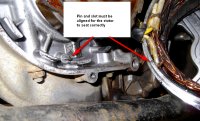
1. I find it easier to pull the alternator right off and set it aside (on piled up wood blocks so it's not hanging from the wiring loom). It's only 2 screws, but you may need a hand impact to get them loose. No need to remove the brushes or brush holder. Then the rotor will be fully exposed for cleaning and testing.

GHoeRsM.jpg


2. For Curley's test, you leave the regulator plugged in. That green wire regulates the ground to the outer brush. You're grounding it full time and turning the alternator on full blast. This shows you whether or not the alternator part of the charging system is working good. It should pump out a good 14 or 15 volts like this, maybe even more, but don't run it long. This is just a quick test to see if it's working up to snuff.

Something else to check is the reg/rec plug. It's located on the left side of the battery box and can be exposed to battery acid and/or battery acid fumes. It can get all corroded.
 
Thank you 5 twins for your excellent advice and the photo is great! I will do just that. If it turns out the reg/rectifier is bad, I have been looking at the one TC Bros has for my bike at $99. Heard anything about that one, or from another reliable source, I would rather buy one than build one I think. By the way, do you know of a good source for new case bolts as I plan to polish the case after repairs are done prior to assembly. Thanks again!
 
I would never spend the $100 or more those vendors want for their combined reg/recs, I would just assemble my own for $20 or less. You're not really "building" these things, they're already made. All you're doing is wiring them up mostly, maybe making a mounting bracket.

I don't replace the case screws unless they're damaged or stripped. What I do is clean them up and paint the heads black. I think the black headed screws look good in contrast to the polished cases.

STZaT02.jpg
 
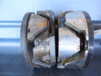
I'll guess that you will find a rotor with low resistance, down around 4 ohms. This is due to failing insulation shorting out sections of the coils. It is a double failure, increasing the draw used by the alternator and reducing power output. Place your leads and keep them on the rings until the reading stabilizes, the reading slowly drops for a couple seconds.
Extremes: bad and good rotors
rotors (1).JPG

stator 007.JPG

XS650charging 013.JPG
 
Many stores now sell stainless metric cap screws. take your old ones along to match up. easy to polish them on a buffing wheel. Doesn't hurt to use a bit of anti seize on the threads.
 
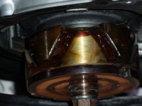
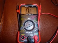
5Twins and gggGary, Hey guys, Well...I opened the left side case and supported the alt housing as you suggested..good tip. Cleaned both rings and everything was looking up...till I took the olm readings on the slip rings of the rotor. Start meter readings 00.2 lead to lead.....ring to ring 01.1 after I held it there awhile, no readings on each of the slip rings to ground using a Innova 3320 digital meter. I ran this test several times You both were right, it was a bad rotor. I am wondering how it even ran and how did it pass the slap test with me using a suspended short 1/2" box wrench? Glad to have found the cause though..Found a new rotor from Racetech Electric for $99 with free s/h, have you heard of them? and will order a rotor puller as well. Have not ordered as yet. So while I am waiting for a new rotor to arrive, are there any more tests I can safely do with a bad rotor? I have read on the forum to not stop at the first failed unit. I still need to solve the issue of not having full volts getting to the brushes, reading 11.4v. Have not checked the key switch pass thru. Where do you do that? Is the wiring inside the headlight perhaps?
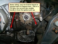
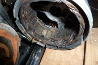
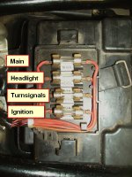
I did take apart and clean the post to battery under the right side cover (it was not bad) and lightly coated each component with dielectric grease. I studied the wiring of the stator that runs along the lower case and no expossed or worn areas found so far. I will clean that whole area and look again to be sure. By the way, the PO converted the old fuse to automotive blade fuse but did not label them. Looking at the diagrams in Clymers I think I have:
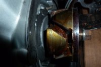
20amp r+r = main fuse, 10 amp ry + ry = headlight, 10 amp br + br= ignition, 10 amp rw + rw = signals/engine stop button is that correct? Thanks guys, I could never have gotten this far without your help. If it turns out the reg/rec is bad as well, I will assemble my own using your guidelines. I am getting a good feeling about this process. This is my 10th bike, but this is my first classic. Never had to do any real work on them other than simple maintenance. This is a nice looking XS650 worthy of getting back on the road and I am looking forward to riding it. Think I will add a few photos to share. Talk to you soon!! P1180983.JPG P1180984.JPG P1180971.JPG P1180969.JPG
 
A shorted rotor will pull down the voltage at the brush.
You can check the diodes in the voltage regulator.
You can ohm out or check voltage drop on the iggy switch at a connector in the headlight bucket.

XS650charging 023.JPG
 
gggGary, I am sooo glad I asked!!! Checked your links and Racetech is out! Any suggestions on a quality rotor source? Found one at Ricks, any thoughts on that one? When assembly time comes, will a drop of Loctite 242 blue be advised on the 2 bolts holding the alternator housing?
Thanks for the info you just gave me on test areas, good to be doing something while waiting for parts.
 
Last edited:
You can check the diodes in the voltage rectifier portion of your combined unit, not regulator. I don't think the regulator has diodes.
 
You guys are so helpful. Great information! I am going to call Gary at custom rewind in Birmingham tomorrow and ask about getting my rotor rewound. In the meantime I will do the testing procedures you recommend because I want to see the current state of the charging system. Hope he is still feeling good enough to work, for his sake as well as mine. If so, I am going to get a quote for the rotor rebuild and the stator due to its age. I already have a new battery, and then assemble a regulator and rectifier like I have seen on this forum. That may be a great way to put this bike back together! Thanks guys, I really appreciate all your guidance. Any further thoughts are always appreciated.
 
Back
Top