Acewell electronic Tach with Pamco - RPM Wiring?

glennpm

Another Old Biker Nut!
Messages
474
Reaction score
63
Points
28
Location
Wiscasset, ME
Hi,

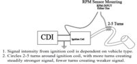
I'm putting an Acewell #2853 on and have a Pamco ignition.The Acewell instructions say to wire to the + terminal of the coil but multiple posts here say to wire to the negative. It also seems to keep the RPM form bouncing, that one or two 1MOhm resistors in series may be required.

So should the wire go to the positive or negative coil terminal when using a Pamco?

The Acewell diagram shows this wiring:
 

Attachments

  • AcewellTachWiring.jpg
    AcewellTachWiring.jpg
    26.8 KB · Views: 1,964
Last edited:
That thumbnail shows two choices. 1 to wrap around the plug wire. Or 2 connect to the coil on the connection that will come from the Pamco

The other wire will go to earth
 
Hi Paul,

Yes, there are two options. I don't want to use the wrap wire option. The other option shows a connection to the positive coil connection. Connecting to the positive doesn't agree with other posts that have been made here for tach connections, they say connect to the negative coil terminal, so I'm wondering which to use. I don't want to risk the wrong connection and screw up the gauge.

Thanks
 
glennpm,

The connection to the positive terminal is to provide power to the Tach. The wrap around thing is there to pick up the pulses. You need both plus the connection to ground.

If this TACH was designed specifically for a CDI (Capacitor Discharge Ignition) then you may experience problems with a conventional electronic system like the PAMCO.
 
glennpm did you ever get this sorted? I am thinking about running a similar setup but may have to pass if it does not work with the pamco.
 
No not quite yet. I'm just about ready to get this thing started up for a test run. I'll let you know how it works out.
 
Glen, I've used an Acewell instrument for over 8 years. The signal wire for the Acewell goes to the same primary terminal of the coil as the signal line from the ignition control (points or igniter box, it makes no difference), you can't get a signal from the powered side. On Japanese negative ground systems you'd hook up to the negative side of the coil, on old Brit positive ground systems you'd hook up to the positive side. A 1/2 amp 2 mega ohm resistor or a pair of 1/2 amp 1 mega ohm resistors will damp the signal nicely. If you need to use 2 resistors join them with stripes pointing the same way, not with same colored stripes facing.
 
Why do you suggest this, I was always under the impression that a resistor was not polarity sensitive.

Resistors are rated in Watts, not Amps, so that should be either a 1/2 Watt 2 meg Ohm resistor or two 1/2 Watt 1 meg Ohm resistors in series, and yes, resistors are not polarity sensitive.

When shopping for these resistors, you may find that resistors below 1 Watt are rated in milliwatts (mW) so look for 500 mW resistors.
 
Thanks guys! Looks like a trip to Radio Shack today. The Acewell came with just one 1meg Ohm resistor which I realized when thinking about projects today, i didn't wire in. I did connect to the negative coil terminal. thinking about it after Pete's early post, there was no way that the power to the coil was going to provide a signal.
 
Resistors are rated in Watts, not Amps, so that should be either a 1/2 Watt 2 meg Ohm resistor or two 1/2 Watt 1 meg Ohm resistors in series, and yes, resistors are not polarity sensitive.

When shopping for these resistors, you may find that resistors below 1 Watt are rated in milliwatts (mW) so look for 500 mW resistors.

Pete, I understand that, my question was why is it necessary to connect them with stripes pointing the same way because, as you confirm, they are not polarity sensitive....or am I still missing the point being made?
 
Pete, I understand that, my question was why is it necessary to connect them with stripes pointing the same way because, as you confirm, they are not polarity sensitive....or am I still missing the point being made?

I don't see the sense in that, but you will have to wait for grizld1 to return with an explanation.
 
Thanks guys! Looks like a trip to Radio Shack today. The Acewell came with just one 1meg Ohm resistor which I realized when thinking about projects today, i didn't wire in. I did connect to the negative coil terminal. thinking about it after Pete's early post, there was no way that the power to the coil was going to provide a signal.

That drawing confuses me. It looks like the signal is obtained from the wire wrapped around the spark plug wire which would then indicate that the other wire should go to the positive side of the coil to provide power to the tach.
 
Yes it is confusing. The wire wrap is if you don't connect to the coil output. The Acewell is not powered from this connection but from a dedicated +12V source.

I found the resistors here:

http://www.ebay.com/itm/10-pack-1-2-watt-5-carbon-film-resistors-2M-ohm-/150471585899?

OK. I see that now in the drawing where it says either or. The power feed just isn't shown. So, that being the case, the wire shown going to the box labeled CDI would be connected to the negative side of the coil, or in the case of the PAMCO, the green wire coil terminal.
 
You want an explanation? OK, here you go. Right, wrong, or indifferent, I was instructed years ago to set stripes on resistors running the same way when stacking them. Guess I could have checked that instruction out with a multitester, but I never bothered as it's done no harm to follow it. Sorry for any confusion caused by my inappropriate use of terms; proper terminology and theory are clearly more valuable than any offering made on the basis of successful experience with the instrument in question, so please excuse my interference with this thread.
 
... I was instructed years ago to set stripes on resistors running the same way when stacking them...

That's actually a de-facto standard practice in the high-volume automated PCB manufacturing process. Axial leaded electrical components are supplied on tapes, or reels, all oriented the same. Extremely important with polarized devices, like diodes and LEDs.
XG_2000_insertion_machine_software_auto_diagnostic_5137_8.jpg


These are fed into sequencers and auto-insertion machines, and we have control over the insertion orientation in the instruction sequence.

Afterwards, manual and automated visual inspection equipment confirms proper PCB stuffing. Having the resistors oriented correctly is a requirement for this inspection. Not for functionality, but so the inspection equipment doesn't reject. Later, in the field, it really helps the techs that are trying to diagnose these boards...
 
Back
Top