Before I start harness can you help organize my approach?

JayR

XS650 Addict
Messages
335
Reaction score
118
Points
43
Location
CT
Good morning boys. I would be grateful if you could help me organize the steps to making an electrical harness for my 1982 XS 650.

I've studied my Haynes manual, gone cross-eyed reviewing the great diagrams and comments in the Tech section, and I am now just dangerous enough to dive in, fire extinguisher by my side.


So a few questions

1) Should I start wiring the circuits in any particular order, is there a benefit to doing any one before another?

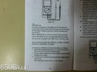
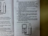
2) As I go along, what is a good way to test my work to determine if it is done properly? I have Mikes XS Probe tester (lights up) and a Radio Shack Multi Meter - but not any good at using them - yet.

3) What type of soldering iron would you recommend that I purchase, is there a "Soldering 101" / or Moto Wiring set up that I should tool up with?

I've googeld around on technique and have read the BASICS - but any motorcycle specific knowledge for soldering would again be much appreciated.


BACKGROUND:
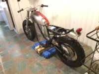
- Custom electronics pan with Li-Ion battery (pics) OK, it is cardboard box that is the same size as a battery. I'm practicing JIT manufacturing :)
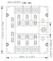
- BEP ATC Fuse block - branch circuit type so not an inline system (diagram)
- Mikes XS starter solenoid, in line Main Fuse
- TC Brothers Universal Ignition Switch
- After market turn signals and headlight - standard stuff
- LED Tail light
- Stock Reg/Rec, TCI, Alternator
- Using stock controls, starter
- Deleting sidestand switch and clutch switch


Thanks again guys!!
 

Attachments

  • E Pan 1.jpg
    E Pan 1.jpg
    39 KB · Views: 260
  • E Pan 2.jpg
    E Pan 2.jpg
    34 KB · Views: 252
  • 3-14-2015 8-23-59 AM.jpg
    3-14-2015 8-23-59 AM.jpg
    32 KB · Views: 250
  • Roller1.jpg
    Roller1.jpg
    113 KB · Views: 254
Wow, we really DO need to get the "Vulcan Mind Meld" button installed.

You may find many of your answers by googling "How to make a wiring harness".

There. That'll keep you busy for a while...
 
well, at least you have a plan..somewhat. When I did mine, I just jumped in. it was my first time, and it was a mess. I redid it 3 times. each time ,it worked, but looked like hell.
The most important thing to do is test each component before you wire it up. Check the rotor, the stator, starter, starter relay.
Then, I found it very usefull to go to home depot, or whatever, and buy about 20 feet of 3 conductor, and 2 conductor wire, the kind used for power tools. its insulated twice, and makes for nice bundling.
Use good connectors, and learn how to crimp properly, don't use that garbage at autozone.
Post up your wiring diagram and well tell you if its ok, or not.
I can post a wiring diagram for the turn signals if you like, looking at a wiring diagram can be frustrating and make your eyes cross, but just follow one circuit at a time.
 
Wow, we really DO need to get the "Vulcan Mind Meld" button installed.

You may find many of your answers by googling "How to make a wiring harness".

There. That'll keep you busy for a while...

Bite my wire - pun intended lol. :D:laugh:

So i have put in the time to get educated on the process, bookmarks and dog ears galore. Just seeking to avoid any "obvious" rookie mistakes out of the gate that aren't obvious until you make them. :wink2:
 
well, at least you have a plan..somewhat. When I did mine, I just jumped in. it was my first time, and it was a mess. I redid it 3 times. each time ,it worked, but looked like hell.
The most important thing to do is test each component before you wire it up. Check the rotor, the stator, starter, starter relay.
Then, I found it very usefull to go to home depot, or whatever, and buy about 20 feet of 3 conductor, and 2 conductor wire, the kind used for power tools. its insulated twice, and makes for nice bundling.
Use good connectors, and learn how to crimp properly, don't use that garbage at autozone.
Post up your wiring diagram and well tell you if its ok, or not.
I can post a wiring diagram for the turn signals if you like, looking at a wiring diagram can be frustrating and make your eyes cross, but just follow one circuit at a time.

Thanks Angus67 - I'd definitely appreciate the turn signal diagram. I've been using the 1982 diagram in my Haynes manual to isolate the circuits, but like you said I get bogged down. I'll take your advice and test the e components first, then pick one or two "runs" to draw up and post.

At Harbor Freight now, let's see what's inside.
 
I'd be happy to gin up some pointers if the members feel it would be useful.

Always a welcome to good info, I don't think there is any on the forum at the moment? A lot of rookie solderers out there, and as you know, it is easy to do a rubbish job of wiring if you don't know what you are doing, or if you have inadequate tools.
 
OK here some advice.... I have made over 50 harnesses for bikes
First get different color wire
second build in steps LIGHT/CHARGING/IGNITION/TURN SIGNAL
Third RED IS ALWAY HOT 12 volts and BLACK is always grounds
Fourth TEST each section of wire you make with the switches installed, I use a battery and a test light and go threw all the wire
LAST buy a 6 pack you will need it.
Good luck with your build and there are many good diagrams on here that will help.
KEEP CHOPPIN
RICH
 
It will take a while! I thought mine would be done in a day, but I found routing the wires takes up the most time! Took me three weekends to get mine done!

A diagram is always a good reference to look at, helped me a lot.
 
Hi JR,
from Fred's How To Bodge Things Book:-
Bigger is better for soldering irons, as well as for other things.
[edit] That's a real soldering iron that gets hot and stays hot when you plug it in, (or even when you lift it off the gasoline-powered blowtorch) those induction thingies are rubbish.[end edit]
Shrink sleeve, cleanliness, lotsa paste flux, thin cored solder, twisting the wires together at the joints and remembering to put the shrink sleeve on first are your friends.
That and a good circuit diagram.
A respected Guru posted that good milspec crimp joints are better than soldered joints but soldered joints are better than the crappy crimps & crimp pliers they sell at auto stores.
 
JayR, In conjunction with a wiring harness diagram, here are some threads that will help.

Wiring harness musings

Soldering Connections

What happens when you turn your key on.

Expanded charging system guide

ELECTRICAL TROUBLE SHOOTING

Wiring diagrams represent the circuits. The thing i found confusing was actually transferring those circuits to the actual shape of the loom on the bike, once i got around that things went somewhat easier. I say some what because i still had brain freeze's and had to walk away and think things through, or just forget about it and come back later and it made more sense

Checking a wiring harness as you build doesn't require any power to test so that testing light is not needed.

Continuity/Resistance testing is the way to do it.
Pages from my multimeter manual on how to set up for this. Set the Ome's to the lowest setting
 

Attachments

  • P1000955.JPG
    P1000955.JPG
    155.3 KB · Views: 229
  • P1000956.JPG
    P1000956.JPG
    169.4 KB · Views: 224
Last edited:
Thanks 2Many, Angus, DaddyG, Fredintoon, Downeaster, Airwolfie, and 650 skull for all of your pointers. Thats what I was Hoping for for to get oriented - gracias. And thanks for the links, I actually have one or two book marked, but forgot about them.

I went to my local West Marine and spent some time in the electrical aisle (call from wife "where are you?", "West Marine", "WTF are you doing there", "Buying a fishing boat").

I was surprised, they have everything with the exception of maybe a loom to build a custom harness. Dozens of different color wire and Guages, fuse blocks, shrink wrap, and dozens of different connector variety packs, individual smaller lacks, crimpers, etc.

http://www.westmarine.com/buy/ancor-marine--primary-wire-by-the-foot--P009_274_001_007

I bought a few lengths of wire and connectors to practice soldering on (borrowed a cheap 30 watt iron from a buddy) and am practicing up using the Wiring Musings info.

You're right, transferring my head from the diagram to looking at the bike was hanging me up. So I picked the left control to focus on, looked at it on the bars with the diagram in hand, and it started to make sense!

Back to West Marine tomorrow for the supplies to do the left control.

Thanks again!
 
Bite my wire - pun intended lol. :D:laugh:

So i have put in the time to get educated on the process, bookmarks and dog ears galore. Just seeking to avoid any "obvious" rookie mistakes out of the gate that aren't obvious until you make them. :wink2:

Haha, y'know, I had a friend that would bite down on connectors to crimp them. Actually saw him open a bottle of Lonestar with his teeth.

On 'rookie mistakes', I guess the devil's in the details.

Proper heat technique and control while soldering is important, a skill you'll have to develop. Too much heat, too long, and some wire insulators will melt back as much as an inch. Not enuff heat, get a cold-solder joint, the rosin can get sandwiched in there and you have NO connection.

If using heat-shrink tubing, plan ahead and slip it on the wire first, else OOPS.
And keep it at least 2" away from the soldering task, or it'll start shrinking where it is.

Of course, there's more...
 
I would suggest getting a decent sodlering iron, preferably one that is temperature adjustable, it makes life-well, soldering!- so much easier! Don't be afraid to spend a little extra money, you WILL use it again, and not just for your bike!!
 
Hey does anyone know what this bullet connector goes to? It is a yellow wire with a Yellow / Black wire that terminates into a single bullet connector. It is the only Y:B wire on the entire diagram it seems - as opposed to B:Y.

I *think* it plugs into one of the two yellow headlight connectors on the diagram.

And thanks again for the tips. Airwolfie I do need a higher watt iron, I'll search around. 2MNy - is a Hemostat basically an alligator clip that I would use to,absorb the excess iron heat to avoid melting the insulation?
 

Attachments

  • image.jpg
    image.jpg
    117.2 KB · Views: 224
Last edited:
I might suggest using wire colors that match the stock colors. This will help when trouble shooting and asking for help on here.
I would start with the most important system first, get it right then add in the next system.
As in the charging system first, your bike won't run long or well with no charging. Next the ignition, Then start on the lighting.
Mount all the parts on the bike where you plan on them being. As you run the wires from part to part you know just how much wire you need.
If you look in the "Some Wiring Diagrams" thread I like #4. It shows the basic points with separate reg and rec. It has the various up grades for the later TCI and combo reg/rec, Just swap the boxes to match what your using. E-start is in upper right corner.
Be sure all grounds are clean bare metal to clean bare metal. A bit of dialectric grease to prevent corrosion.
Same with all plug together connections. I tend to like plug together connections on the parts, that makes trouble shooting and replacement easier.
Leo
 
Jay, hemostat, sure, that'll work as a heatsink. Can also dampen a small strip of paper towel, and wrap it around the insulation near the connection. Still gotta be fast, tho'.
 
Y/B should be coming out of the turn signal switch and into a 6 pin plug, (female), that connects up to a Y on the Male plug.

If yours has bypassed the plug then it can go straight into a headlight connecter. Should be a double bullet connector that has a single wire to the headlight.

Yours has the 2 wires, (Y..Y/B), on one bullet connector

Yellow, (Y), is the power wire from the Generator to headlight and Taillights
 
Leo Like your idea on matching colors but in my search I just have not found a vendor that will sell 25'-50'100' of wire like that. Most wire company's want large orders 1000' or more and when you are spending that much money you cannot keep cost low.
If anyone on here knows of a company that sells 16 gauge or 18 gauge wire like that I would really like to get into contact with that company. I found one company but wires are attached like rib style for computers. That would be great to have the colors the same as the stock manual. I just found a company that is giving me like 15 different colors so I ordered from them and waiting to see product.
My suggestion is if you are not changing anything on bike but harness BUY a Stock one from Mikes for around $75.00 but if you are doing away with a lot and just trying to make a bare bones one do it yourself so you learn or buy one of my Harness kits that saves you some time and you still learn. You can't go out and buy 7 different color wires - shrink tubing for the cost I sell them. Most wire 25' is $6.00 roll and shrink tubing is $6.00 25' roll . So that's $48.00 and you have to do labor. Mine are $55.00 SHIPPED in USA. There should be a wire kit replacement from the maker but they just sell harnesses complete too. ANYONE GOT AND INFO ON wire company that sell more than just solid colors please let me know.
KEEP CHOPPIN
Rich
 
Last edited:
Back
Top