Charging system help

kuthe64

XS650 Enthusiast
Messages
61
Reaction score
1
Points
6
Location
Nashville TN
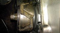
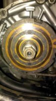
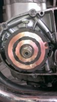
I have read the tech section on trouble shooting the charging system, and im hung up on the rotor.

Ive used three different multimeters on the rotor and cannot get a reading at all.(ive cleaned it)
When reving the engine to 3,000 rpm the voltage does not go up at all.
I replaced the brushes.
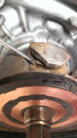
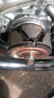
The slap test was unsuccessful, but to make sure I was doing the slap test correctly I pulled off the stator and turned the key on to test the magnetic field. I put a nail (about two inches long) and it would barley stick to the shaft of the rotor. Im assuming the magnetic field
Stock, 1980 or later, and the headlight doesn't light at all?
should be much stronger than this, does this mean that the rotor is bad?

"You may not have any charging, the headlight is controlled by a relay that is powered directly from the stator, no charging, the relay won't close, no headlight. "
I read this in curlys trouble shooting guide and my headlight does not come on, how would I fix this?

Thank you in advance, and also thank you to everyone that has helped me this far.

81 xs650
 
Last edited:
OK XS650 charging 101; the rotor is an electromagnet. The brushes and copper rings supply 12 volts to the internal coil, the coil creates a magnetic field, no voltage, no magnetism. That's why I had you checking for a broken solder connection where the coil wires attach to the rings on the back of the phenolic. Why the new thread?

There are two failure modes on rotors;
The first and most common is that the insulation on the coil wires has started to break down, this "shorts out" sections of the coil. REDUCING resistance from the normal 5.6 ohms or so and increasing the current flow, this causes a low or no charge condition. Anything under 5.0 ohms is considered failed.

The second failure mode is less common and is a broken wire or solder connection stopping any current flow also stopping charging.
 
So when you say "check for a broken solder connection where the coil wires attach to the rings on the back of the phenolic." That would be what goes around the rotor what I was refering to as the stator(Where all the copper wires are bundle up)Sorry for all the dumb questions but I'm learning as I go I am by no means a mechanic or understand all that much about charging systems. Thank you for all your help so far.
 
Sorry it took so long I had to go take photos and mark them up.
See if these help.

rotor3.JPG rotor1.JPG rotor2.JPG

Do NOT attempt to remove the rotor until you have the proper tool.
 
Thanks that helps a ton, never would have figured that out without those pictures. I'll get out to the shed and check out the rotors tomorrow and let ya know what I find. Do you sell them if mine is bad?
 
looks like a fried rotor to me but ill definitely get some opinions first.
 

Attachments

  • IMAG0991.jpg
    IMAG0991.jpg
    166.2 KB · Views: 74
  • IMAG0990.jpg
    IMAG0990.jpg
    154.6 KB · Views: 74
  • IMAG0984.jpg
    IMAG0984.jpg
    160.2 KB · Views: 91
  • IMAG0982.jpg
    IMAG0982.jpg
    164.8 KB · Views: 69
  • IMAG0981.jpg
    IMAG0981.jpg
    138.3 KB · Views: 53
  • IMAG0979.jpg
    IMAG0979.jpg
    135.5 KB · Views: 63
Those rings look all varnished up or coated with a carbon oil mix or something, hit em with 320 grit till they are bright copper colored. test again.
 
Check from both slip ring to slip ring and from the slip rings to the nut that holds it on. 5 ohms ring to ring is good. Rings to nut should be infinity.
Leo
 
So i sanded it with the 320 paper and I still could not get any readings.
From ring to ring I got nothing and from ring to nut I also got nothing. I have three multimeters with brand new battery's in them and none of them could get a reading. What did change after I cleaned it was when I put both leads on the same ring I got 0.2 instead of it jumping around everywhere.

Also in the pictures you can see a piece actually flaking off, and there is no varnish at all on about half of it.
 

Attachments

  • IMAG0994.jpg
    IMAG0994.jpg
    201.9 KB · Views: 57
  • IMAG0995.jpg
    IMAG0995.jpg
    144.2 KB · Views: 75
  • IMAG0996.jpg
    IMAG0996.jpg
    182.1 KB · Views: 60
So i sanded it with the 320 paper and I still could not get any readings.
From ring to ring I got nothing and from ring to nut I also got nothing. I have three multimeters with brand new battery's in them and none of them could get a reading. What did change after I cleaned it was when I put both leads on the same ring I got 0.2 instead of it jumping around everywhere.

Also in the pictures you can see a piece actually flaking off, and there is no varnish at all on about half of it.

Your rotor coil is open circuit. As Gary mentioned, you can try investigating a possible broken enameled copper wire at the 2 locations where the coil wire connects to the slip rings. The 2 locations are 90 degrees apart at the cut-outs in the phenolic.

Several years ago, I received a rotor from a member that said it was open circuit, and was defective. I did some looking around and found 1 end of the rotor copper wire had broken off from the slip ring connection point. I cleaned up the area and re-soldered the wire back on and resulted in a 5 ohm measurement, so the rotor was working once again.

You could try using a soldering iron to melt away the excess solder and try to view the rotor copper wire. If you can find the end of the broken wire, its worth a try to resolder it back onto the slip ring lug.

The rotor is bad now so you have nothing to lose by trying to find the end of the broken wire. If you find that both ends are still connected to the slip ring lugs, then of course the coil wire is open somewhere inside the coil itself.
 
Back
Top