-
Enjoy XS650.com? Consider making a donation to help support the site.
XS650.com receives a small share of sales from some links on this page, but direct donations have a much greater impact on keeping this site going.
You are using an out of date browser. It may not display this or other websites correctly.
You should upgrade or use an alternative browser.
You should upgrade or use an alternative browser.
Check out my wiring diagram for me
- Thread starter Take Warning15
- Start date
Take Warning15
XS650 Addict
Any electrical geniuses out there?
Your diagram is a little hard to read, but with a quick look, I see the ground for the Pamco is missing. A 7.5 amp fuse would be better, for the Pamco ignition, than the 10 amp fuse you show.
Your neutral switch shows a black wire connection, when in fact the neutral switch gets its ground from the engine itself.
Your diagram shows rec/reg wiring for the 80 to 83 years. If your bike uses ungrounded brushes, then that is fine.
Why don't you take the time to read through the "Wiring Diagrams" thread that is in the "Tech" section. 28 pages of related information.
Last edited:
Along with what RG said, where the red wire comes up from the reg/rec, it should join with the red wire from the battery then hook to the main fuse.
On your turn signals the LED can not go between the flasher and turn switch. I assume this was intended to be an indicator. It won't work that way. You need two led's hooked up after the switch. One for each side. Or one led with two diodes hooked to each side, hooked together then hooked to the led. The other end of led hooked to ground.
You have an oval labeled led above the yellow brake wire. If you want it to light it needs a ground. One question why an led there?
Where the arrow points to where the two brown lines cross should be a connection. No connection no power goes to anything but the ignition.
Leo
Take Warning15
XS650 Addict
My bike has a single rectifier/ regulator. I'm pretty sure that is how it is wired currently. I did read that thread before starting my own. I only started my own because I could not find on that had the same setup as me.
Take Warning15
XS650 Addict
Let me make a correction. I do have a grounded brush (I believe) but a single regulator/ rectifier unit.
Let me make a correction. I do have a grounded brush (I believe) but a single regulator/ rectifier unit.
Your diagram is wrong then. Refer to the "Wiring Diagrams" thread, that shows a grounded brush.
The grounded brush can work with a combo reg/rec IF the reg/rec is designed to work with a grounded brush. Mike's sells them both.
Now in his diagram it does show the 80 up reg/rec set up on the brushes. One wire is green the other is brown. Neither brush is grounded.
The 70-79 had a green wire on one brush, a black wire on the other brush. The black wire is the grounded brush. The brush grounds to the stator. The black wire goes up into the harness and hooks into the harness ground.
I'm sure if you looked through all the "Some Wiring Diagrams" thread you would find one that uses the things you have.
The most important part of any diagram is the charging system. Without it right the rest won't matter. Once you get the charging system figured out add the ignition.
Now it should start and charge the battery. Unless you use a PMA and a Cap. then it should run and not charge over 14.5 volts.
Once you get thing that far adding the other things is easy, add a fuse some wire and switches to control what you add.
Leo
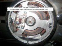
Here's some pics to look at. One is the 70-79 brushes, the other the 80 up.
If you look closely at the pics you will see the black wire on the 70-79 goes up and hooks to the upper left screw side screw. Screw #1.
This is the pic pointing out the three screws that get changed to nylon with the three screw mod.
On the 80 you will see the brown wire comes up to and over to the upper right side wire.
Leo
Attachments

...where the red wire comes up from the reg/rec, it should join with the red wire from the battery then hook to the main fuse.
You should not do this. If things go wrong in the reg/rec or in the wires it may short circuit the battery to ground. This may cause melted wires, sparks, fire and other nasty stuff. You have it right in your original pic: battery -> main fuse -> everything else.
Pekka
It's best to have the main fuse between the power source and the rest of the system. On these bikes Or any bike the power source is the charging system and battery. If you use a PMA and cap then those are the power source.
On the stock system the reg/rec won't go wild if the battery gets disconnected from the charging system. If it does the system just stops working.
On a PMA disconnecting the cap or battery from the PMA lets the reg/rec go uncontrolled. Causing very large voltage spikes to pass to the system.
Hooking the positive from the reg/rec is fine.
Having the fuse there if it blows it may or may not stop the power flow from the alternator. On the stock system if there is enough residual magnetism in the rotor it will keep on producing power. If this happens might not even know the fuse has blown.
Leo
On a PMA disconnecting the cap or battery from the PMA lets the reg/rec go uncontrolled. Causing very large voltage spikes to pass to the system.
Hooking the positive from the reg/rec is fine.
Leo
Sorry to disagree again with you Leo. But I do not think that this is true.
People have run PMA's with no battery or cap. I had one in my dirt bike. It is not true that the reg wont regulate w/o battery/cap. Unless it is a really bad (as in low quality) or faulty reg. Usually a PMA regulator works by shorting the PMA coils if the voltage rises above a threshold (see this pic: http://4.bp.blogspot.com/_DzKoXJZ8-...M/GkO36tQz9Uo/s1600/three+phase+shunt+reg.GIF). Not having a battery or cap produces a nasty waveform but will regulate anyway.
Not using a fuse after a between battery and load is not fine. Unless you want to risk destroying the battery and possibly setting something on fire. EDIT: With just a capacitor it is fine.
I will work either way. But as they say, "dress for the crash not for the ride"?
Pekka
Take Warning15
XS650 Addict
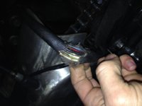
So I've been working and reading, but I'm pretty confused. I updated my diagram like this: three white wires from the alternator to the reg/ rec. Red and black(ground) going brushes to reg/ rec and a final red wire going from reg/ rec to the battery and key. However, I'm looking at the bike as it is currently wired and this is what I see. I've got wires unaccounted for from the reg and rec. The other picture is of the wires coming from the alternator.
I believe the blue wire goes to the neutral switch, the black to the brush, and red to the other brush. The yellow will be unused. It seems I have at least one unaccounted for wire. This assumes the previous owner changed the colors of the wires at some point in the harness and they actually go where they should. I'm looking at the original wiring diagram and the colors are again, different.
This all being said, the bike does run and charge. The reason I'm rewiring it is because I've eliminated a few components and keep blowing fuses.
Attachments

Don't know if this helps but anyway: I'm not sure what wires are coming from your reg/rec but the stock wires from the alternator should be: 3 x white (stator coils), yellow (center point of stator coils, used to see if the motor is running), black (ground), blue (grounded when in neutral gear) and one for the positive brush (don't remember the color).
I found that a good indication of the alternator working was to measure the brush voltage while the motor was running at different engine speeds. If I remember correctly the voltage should drop when rev's increase.
Which fuses are blowing?
Pekka
I found that a good indication of the alternator working was to measure the brush voltage while the motor was running at different engine speeds. If I remember correctly the voltage should drop when rev's increase.
Which fuses are blowing?
Pekka
Take Warning15
XS650 Addict
I'm sure it is charging. I rode it 400 miles last week and also have put a voltmeter on it. With the way the last owner wired it, there is only one 20 amp fuse on the positive lead from the battery. This is another reason that I want to rewire.
Take Warning15
XS650 Addict
Take Warning15
XS650 Addict
The only change I want to make is eliminating the reserve lighting module, or light checker. I want to take that entire circuit out. Any problem with that?
Take Warning15
XS650 Addict
Would it be acceptable to go reg/ rec, fuse, battery/ ignition, in that order? instead of reg/ rec, then split to key and another way to a fuse and then the battery?
On the positive wire from the reg/rec, you can put a fuse between the reg/rec and battery, I don't.
I run this wire straight to the battery positive.
I then run a red wire off the battery positive to a 20 amp fuse, to the main switch. From the main switch to the rest of the fuses.
The main fuse should be between the power source and as much of the electrical system as you can. If it blows you want all power to stop. If your main fuse is between the reg/rec and battery if it blows the battery will still send power to the rest of the system.
On any thing, the power source is the battery and the alternator. You need the main fuse between these and everything else.
Leo