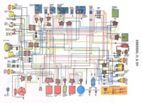
On the diagram the switch boxes show which color wires come into the boxes. Along one side of the box are the switch positions. Across the box are smaller boxes with dots connected by lines. This show which wires ae connected in each position of the switch. Lets start with an easy switch, the horn button . It shows a pink wire coming up to it on one side and the other side to ground. When you push the button it hooks the pink wire to ground. Now find the horn, follow the pink wire to thye horn. At the horn you will find the pink on one side and a brown on the other. If you trace the brown back you will find it goes to power after the key switch. It goes to other things as well but all that's important is it goes to power. Power flows on the brown to the horn, from the horn on the pink wire to the switch, when you push the button it grounds the pink wire completeing the circuit and the horn toots.
You can do the sdame with the other switches. Like the dimmer switch. Power come in on the yellow/blue wire. You can see that when the switch is in either hi or lo it connects two of the wires. In the low position power flows out on the green wire to the low beam of the headlight. In the high position power flows on the yellow wire to the high beam. This is on the left side of the switch, the connections on the right side go to the reserve lighting unit and are used to turn on one beam of the headlight when the other fails. The RLU also lights a warning light on the dash.
THe turn signal works very simular, the left side runs the lights the right side hooks to the self canceler to turn them off.
When you have a problem like when you use the front brake the brake light doesn't light. You look at the diagram, trace the brake light wire, it's yellow, from the brake light forward and you will find it comes out of the light in two places because you have two bulbs, they join and go forward and go to the rear brake switch, it also goes forward to the front brake switch. You will see a brown wire on the other side of both brake switches. As before the brown wire goes to power. This power flows to the brake switch, when you use the brakes the switchs send power to the brake light. So if your front switch isn't lighting the brake light you need to check to see if power is going to the switch. Unplug the brake switch wires and use your meter to test for power on the brown wire. If you have power, use a jumper to hook the brown to the yellow. This bypasses the switch and sends power to the brake light If the light lights doing this it means the switch is bad or the connections are bad. Clean the connections and plug it back in, test the brake light. If it works, good, if not change the switch.
I hope this helps you understand how to read a diagram and how it can help fix electrical issues.
Leo