Hey guys new to the forum. Starting rewire in a couple days. 81 tci engine. Rewireing from sccratch, my question is all bobber harness diagrams I read have a main generic keyed switch but then there is a seperate kill switch prior to the coil. Is this necessary or strictly for safety. I understand the safety factor but want a bare bones as possible harness. Bike will be kick only and is stock ignition. I just want to know if I can run only a key switch and still charge as it should thanks a lot guys.
-
Enjoy XS650.com? Consider making a donation to help support the site.
XS650.com receives a small share of sales from some links on this page, but direct donations have a much greater impact on keeping this site going.
You are using an out of date browser. It may not display this or other websites correctly.
You should upgrade or use an alternative browser.
You should upgrade or use an alternative browser.
key switch and kill switch?
- Thread starter zig917
- Start date
-
- Tags
- electrical
Hey guys new to the forum. Starting rewire in a couple days. 81 tci engine. Rewireing from sccratch, my question is all bobber harness diagrams I read have a main generic keyed switch but then there is a seperate kill switch prior to the coil. Is this necessary or strictly for safety. I understand the safety factor but want a bare bones as possible harness. Bike will be kick only and is stock ignition. I just want to know if I can run only a key switch and still charge as it should thanks a lot guys.
Yes its necessary, and yes its for safety.If you understand the safety factor, then you know why its needed.
The key switch and kill switch have nothing to do with charging.
If you want to toss safety out the window, then don't use a kill switch. Its your choice.
Its an alternator system. Key off there is no power to the feild coil.
As long as your reg rec is good its a one way street out of the box
You dont have to run the kill switch..
but say you get run off the road and your pinned under a bike, stuck on full throttle and cant reach the key. Happened to me when i was a kid.leg was between fender and wheel,arm on pipe. Better safe than sorry dude
Posted via Mobile
Is there a reason that the key switch is not directly in line with the red wire feeding the reg. rec. Its actually on a T that branches before the reg. So the reg rec always has juice? What's the point of this?
The battery and the rec/reg are both sources of power. The power flow is from either, and flows through the key to the various loads.
The rec/reg does not always have power. The red wire is coming out from the rec/reg, not feeding into it. The red wire is coming from the rectifier section only. The rectifier contains diodes (one way switches), which only allow power to flow outwards toward the key and not inward to the rectifier.
So the key switch has to be on that branch and not directly in line with the reg? Sorry for all the dumb questions guys just trying to understand how this all works.
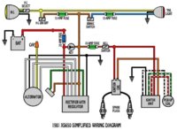
The circuit is correct as shown. It only shows one brake switch, but it should show 1 for front and 1 for rear.
edit: The 10 amp fuse for the brake switches, should be wired before the brake switches, not after the brake switch.
Last edited:
So the red wire from the battery feeds the key, and the red from the rec feeds power back to the battery. That was my next question where do I put the front brake switch in that circuit. Do I just run something desperate to the brake light or can I tap in to the same circuit the rear switch is on? You guys are a huge help.already learning so much!
So the red wire from the battery feeds the key, and the red from the rec feeds power back to the battery. That was my next question where do I put the front brake switch in that circuit. Do I just run something desperate to the brake light or can I tap in to the same circuit the rear switch is on? You guys are a huge help.already learning so much!
The battery red wire is a 2 way street. Current can flow out of the battery, and current can flow into the battery. The red wire from the rec/reg is a one way street; current can only flow outward from the rectifier. The igniton key only passes current one way, towards the different loads.
For brake wiring:
Take a look in the "Tech" section.............."Wiring Diagrams". The 2 brake switches are a parallel type wiring. Spent some time and learn to read wiring diagrams................its a must for these old bikes.
I know these were originally intended for the GS but I think it is also representative for a discussion of the "T" configuration for the battery-R/R. The 15 amp main fuse, is typically a 20 amp fuse on the XS650.
These are the typical currents you see in a GS; the battery charging fuse box arrangement is nearly the same between the two.
Note these are all nominal values, but they are representative of the scope/current clamp measurements I have made.
In reviewing my notes, the 15 amp main fuse is carrying at maximum 11 amps average (when engine is not running) so the 20 amps typically installed on the XS650 would really be over sized.
I know these were originally intended for the GS but I think it is also representative for a discussion of the "T" configuration for the battery-R/R. The 15 amp main fuse, is typically a 20 amp fuse on the XS650.

In reviewing my notes, the 15 amp main fuse is carrying at maximum 11 amps average (when engine is not running) so the 20 amps typically installed on the XS650 would really be over sized.
Just want to add, point #2 is the reason to put the fuse after both the rec/reg and battery and not simply between the rec/reg and battery. There is no protection to your wiring when the bike is running should your rec/reg decide to not work properly.
Just want to add, point #2 is the reason to put the fuse after both the rec/reg and battery and not simply between the rec/reg and battery. There is no protection to your wiring when the bike is running should your rec/reg decide to not work properly.
A little more discussion may help understanding the "T" configuration.
You can fuse the output of an alternator, but in the case of typical motorcycle the maximum current that can be provided is limited to about 15 amps. So in effect an alternator is "self limited" due to the finite charging capacity making a 20 amp fuse unnecessary for the alternator output.
On the other hand a direct short on the battery will yield current limited by only the internal resistance of the battery which can get close to 100 amps or more.
If the electrical system has a fuse box for power distribution down stream of the "T" then the need for fusing the alternator is even further reduced.
One other point to make clear and that is that a primary failure mode to be concerned with is a shorted rectifier diode to ground. In that case you absolutely need a fuse between the battery and R/R to avoid a melt down.
In the diagram I show, the RED connection between the R/R, 15amp main fuse, and ignition switch is the "T" and the corresponding connection point on the BLACK return is a "Single Point Ground" (SPG).
Just an FYI, the charging output of the later `80-`83 models is rated at 14v 16a.
1980 model manual excerpts:
Most of my comments are related to actual measured GS loads and not what the rating is of the charging system. So for typical, 3-4 ohms coils, incandescent lights, blinkers, and headlamps the loads for most street legal non-EFI motorcycles are going to be pretty similar. That rating is very similar to the GS Suzuki's.
The GS Suzuki's are rated at about 220 watts as I recall with a typical 14.5V which is 15.2 amps but this is probably more the total loads than the actual charging capacity. I know there is more current available if demanded by extra accessories (e.g. glove warmers). Without looking I don't quite remember but it could go as high as 18 amps at a similar 4K or 5K RPM.
Similar threads
- Replies
- 28
- Views
- 2K
- Replies
- 6
- Views
- 497
- Replies
- 10
- Views
- 1K