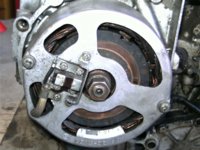
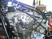
Miss November XS2 tribute

5T, once again indebted for your wisdom & experience. I don't intend to refit the sprocket, or at least not to tighten it, until I have the motor back in the frame. So that I can fit the chain to hold things. But I will make a note to use sealer as you show.

At the moment, just taking my time and doing little jobs. Today, attended to the engine wiring. It had the 6-way block connector, but my revised system uses bullet connectors. So, hacked the block off and fitted bullets. Even added a spot of solder on each to hopefully ensure good continuity. Then replaced the brittle old sleeve with a length of heat shrink. Have put the harness clip back in its proper place and peened the casting to hold it.

This lockdown means plenty of time . . .
 
Dealing with another small issue - the pickup wires to the Boyer box.

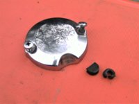
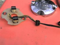
On the 447- engine, a grotty rubber ring had been hacked up and pressed into use (literally) to house the wires as they exit the 'points' housing.

The 2F0- engine has a semi-circular rubber blanking plug to fill the gap in the 'points' housing because there's no wires exiting there.

To save 1000 words:


PICT2123.JPG


Don't want to use the grotty ring. Thinking whether to modify the rubber plug by filing a slot to accommodate the two wires. The rubber plug has Yamaha part no 9033812044 and is discontinued. Is there an alternative plug from an earlier model with timing wires exiting in that area?

Looking at CMSNL's web site, the plug was supplied fitted over the wiring on the contact breaker assembly . . .
 
When I installed my Pamco, I took one of those solid factory plugs and simply drilled a hole in it. Being old, it was hard and pretty easy to drill. First I tried removing a plug from some factory points wires but it wasn't budging, so I modded a solid one .....

uKgTNI9.jpg


lqnTgVq.jpg


Since I was doing the install from scratch, there were no crimps on the Pamco wires to begin with. That allowed me to easily stick the wire through the hole I'd drilled. Then the crimps were put on the wire ends.
 
Yes, I thought of doing it that way. But the wires are soldered on the Boyer plate, then they share an outer, then bullet connectors. So, the simple option is file a slot to pass the wires though.

But I guess I shouldn't be lazy. Drill a hole, cut the bullets off, strip the outer - which should be easy enough - feed the wires, put some heat shrink, new bullets . . .

Just need to check I have coupla spare bullets connectors.
 
If the rubber is soft, put it in the freezer overnight and it'll drill just like metal. Doesn't work for all compositions of rubber though. Not sure if it will work on that plug.
 
If the rubber is soft, put it in the freezer overnight and it'll drill just like metal. Doesn't work for all compositions of rubber though. Not sure if it will work on that plug.

In fact, the rubber is old and stiff, just like meself. Able to drill two 2.5mm holes in close promiscuity and push the wires through:


PICT2125.JPG


The ends had spade connectors - there's a few somewhere in the garage . . .
 
Now this is probably XS650 101 but, well, live & learn?

Today, with an assistant still prepared to make herself useful in the garage - even thought things are sometimes, uhm, terse - lobbed the 2F0 motor in the general direction of the frame. So glad I bought that block & chain.

Thinking ahead, always a tight squeeze to get the carbs in, decided to push one bolt only through. With the lower bolt in place, the engine can be tilted forward, leaving plenty of space to manoeuvre.

Except it was very soon clear they would not fit. Doh, the '80 bike must have carried 34mm carbs? Went through worriting about the cylinder head casting. Are they the same? Is the inlet the same size? OMG, might need another set of carbs to do this engine swap?

Pulled an inlet rubber off each engine to compare:


PICT2127.JPG


Clearly, the one off the 447, l/h in the picture, is much larger that the 2F0 item. But the good news is they seem to be the same diameter where they meet the head. That's the side you can't see in the picture.

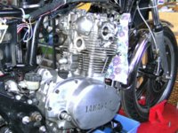
So at the moment, bike looks like this:


PICT2128.JPG


Think I'm back on track. Swap the inlets, fit the 38mm carbs, fit the rest of the engine bolts, etcetera.

But what is the next unexpected problem?
 
I think I would have added some sort of protection sleeve over the Boyer wires, similar to what the Pamco and stock points wires have, and run it through the rubber plug like they did. The wires end up running along and sitting right on a hot cylinder fin .....

BuyQCH7.jpg
 
Great minds - I've encased the two wires in heat shrink from the rubber plug to just short of the spade connectors. Might spot it in the photo, hanging down just behind the l/h inlet.
 
Well yes, that's good, but on the stock set-up and the Pamco, that protection extends through the rubber plug.
 
That regulator from Cargo is good quality. You can buy cheaper from China(£6) but Cargo has a good name. Having its own heat sink makes life a lot easier. When I tried one I found that it regulated at approx. 14.4 - 14.7V. I am interested to see what you observe. Just remember the Red wire on the regulator is also the reference voltage wire so it is important that the voltage measured across Red and Ground is very close to that directly across the battery terminals.

Edit: The Cargo regulator is set to control at 14.5V.
 
Last edited:
New engine is in, all bolts loosely fitted, but not yet torqued up. And carbs fitted using the 'old' inlets.

Thoughts turned to setting the timing and I'm unsure about the timing marks on the new engine:


PICT2129.JPG


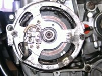
Perhaps not too clear in above photo but there is a single mark with a 'T' near the rotor mark, which might be TDC? Then ahead of that there's a 'square' mark near the faint circle on the rotor casting. That's not far enough to be fully advanced. But there isn't anything else further ahead.

To compare with the old engine:


PICT2130.JPG


Again, the picture not very clear. But in the white painted region there's a TDC mark on the right, then a mark with an 'F' which I take to be fully retarded, then much further ahead on the left is the fully advanced mark.

Am I reading the marks wrongly on the new engine? Is the little timing plate the wrong one? Or are the CDI engines set at retarded only?

Another question, I think the plug leads are too long:


PICT2131.JPG


The left-hand one loops back as far as the congested area near the fuel tap where it competes for space with the petrol pipe, clutch cable, throttle cable, etc.

The right-hand lead is the same length and can be seen sitting on top of the carb.

Should I just cut them a bit shorter?

Next, will have to figure out how to make a mounting for the new regulator.

But hey, the sun has been out today, everybody is in lock-down, guess I'm lucky to have rebuilding an old bike to mess about with.
 
The little timing plate is correct on the newer engine. Yes, that mark on the far right by the "T" is TDC .....

zqzmpBb.jpg


The "U" shaped mark just to the left of it represents your idle timing "range", about 13° to 17° BTDC .....

EZAK4dP.jpg


Many of us like running it to the right (retarded) side of the "range", so at like 12° or 13° BTDC. This motor seems to perform a bit better at higher RPMs like this and it wards off pinging .....

brRhheT.jpg


There is no mark given for full advance but you can use the left side of the drainage notch on the cover .....

dCOdJnb.jpg


Yes, your plug wires look to be a bit long, I would shorten them up a few inches .....

L9xI2JZ.jpg
 
Yes, the TCI engines just have the TDC mark and the fire mark (or 'square' in your case) at full retard. Since advance was done electronically, Yamaha didn't see the need for the advance mark. You could measure from the old stator and scribe an advance mark.
 
Yes, the TCI engines just have the TDC mark and the fire mark (or 'square' in your case) at full retard. Since advance was done electronically, Yamaha didn't see the need for the advance mark. You could measure from the old stator and scribe an advance mark.
 
5T, thank you once again for a very comprehensive answer. Will follow your advice and set the timing at the retarded end of the range. Provided the, ahem, inexpensive strobe I bought gives a clear signal.

I'll give the plug leads a snip. Never had to shorten plug leads before so glad nobody saying 'Oh no, no, no - you don't want to do that!'

Jim, will do what you suggest and add a mark at the advance position. Do you happen to know if that would be the same figure as for the 447 engine?

Onwards and upwards.
 
When I do plug wires, I like to prep the ends like so to insure good contact. I snip about 1/8" of insulation off then fan the strands of the wire out in a radial pattern. Then I install the plug cap or the wire into the coil. I brush the end of the wire with a little dielectric grease as well .....

VqkZjYD.jpg
 
Back
Top