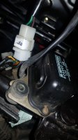
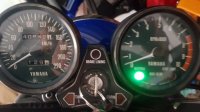
New French (blue) member

The ref I ordered is OK, according to the Yamaha ref.
Do I have to follow the schematic I join, i. e. plugging the brown wire on the red coming from the battery?

Assuming that is the right Reg / Rec and the right wiring
3 White should be easy to find
1 red from battery to the left. of them That one is the charging current
1Brown via the Fuse and ignition lock power in
2 left one ground ..don't think it matter that much where it connects to ground
1 green to the brush upside

Should be possible please come back if you don't have the same colours
The green to the brush I believe is not there yet.

n.b Red and Brown are not connected brown gets disconnected via Key
the red don't

After connecting see if you have 12 V or so on the green brush
 
Thanks Jan, I feel sorry to be so uncapable.
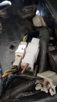
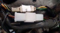
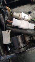
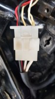
I post some pictures.
I am ok with the connector that gathers the 3 white, the black and the red.
I am confused with the wires coming for the "old" regulator i.e. 1 black, 1 green and I brown.
I don't understand why I should connect the brown to the fuse box and the green to the brushes, instead of just plugging the new connector in the one coming from the "old" regulator.
I tried the "slap test" once everything connected, and it did not work.

20210724_114855.jpg 20210724_121852.jpg 20210724_122135.jpg 20210724_121801.jpg
 
Last edited:
Thanks Jan, I feel sorry to be so uncapable.
I post some pictures.
I am ok with the connector that gathers the 3 white, the black and the red.
I am confused with the wires coming for the "old" regulator i.e. 1 black, 1 green and I brown.
I don't understand why I should connect the brown to the fuse box and the green to the brushes, instead of just plugging the new connector in the one coming from the "old" regulator.
I tried the "slap test" once everything connected, and it did not work.

View attachment 195303 View attachment 195304 View attachment 195305 View attachment 195306

No worries it can be tricky with the electrics
Not sure I understand the problem
So the 3 white and red .. black are there

Mr 5T has it
These combined units only have one ground wire and it gets shared between the regulator and the rectifier. So, you needn't worry about the "missing" black ground wire in the new unit's regulator plug. The new regulator will get it's ground from the ground wire in the new rectifier plug.

upload_2021-7-24_19-7-35.jpeg

There are now connected R / 3x W / B
There are only 2 pins left Brown and green to connect according to Schematic..
Why it is different from the solution before ??? Is impossible to know it depends on the internals of the " Black Box "
That can entirely different from the previous solution.
If one connects a microcontroller one does it so according to the wiring and specs and leave it by that or strictly to the electronics engineer
It can be to difficult to understand the internals

If i get this right
instead of just plugging the new connector in the one coming from the "old" regulator.

Since the new unit has both regulator and rectifier the old Regulator is off the bike perhaps in the dust bin
Consequently there can be no Wires coming from the Old regulator it is taken off
The brown and green from the brushes and key goes in according to Schematic above


Thanks to Jan_P and 650Skull.
Why are the user manuals not written in French, ah ah.
I will try this, i.e. connecting the green wire to the black wire (if I understand what I read).

I printed the 4 pages "fault-finding flow chart" from the ElectroSport website and I am afraid of what I read.
 
Last edited:
OK I am on it
I am not sure what R/R you have
I believe your bike is a 77 D North American model then the Schematic is that one

https://thexscafedotcom.wordpress.com/2012/02/26/xs650-77-xs-d-wiring-diagram/

upload_2021-8-14_17-6-47.png


Far left is the alternator the round thing is the stator winding and the small one at the right of the circle is brushes to rotor
next to the right is neutral switch and is not involved here
Next to the right is rectifier and the next is regulator the mechanical one stock ---2 separate stock but on the new one ..one unit only

Since I am not sure what R /R it is but as a first assumption and Your post # 94 one can clearly see 2 connectors
It appears to be right as in there
https://www.xs650shop.de/en/electric/1040/regulator/rectifier-unit?number=24-2089

Now the first assumption would be that the regulator rectifier is a plug and play unit
Looking at your post # 94 there are 2 Connectors

And that would be those


upload_2021-8-14_17-16-59.png


Now please inspect the parts that was sitting on the bike ,,with the new combined R/R are the colors the same
On the old and the new
.. Since they are of different sizes it is not possible to connect wrong unless it is the wrong R /R
( there is a never version for post 80 -bikes )

If colors check out and it looks as a working correct part please ensure that the connection plugs are in properly and and that there is no corrosion or dirt and that the pins are sitting in their proper position. I use copper grease but there are other alternatives : The point is that there must be electrical contact
Please do that inspection several times and post pictures if uncertain since if polarity is connected wrong these can burn faster than anyone can spell " Blue Smoke "

If you feel it is right ( after the Checks ) and the plugs are sitting a startup can be tested with a Voltage Measurement across the battery

To sum it up
If you got the right R /R for a pre 80 bike .I cannot see any reason not working if the connectors are sitting OK

The rotor is famous for frying so the slip ring Resistance is a suspect. And something to check

The link to the sellers description of the R /R would help so we can be certain it is the right one I myself was sold the wrong one from a Chinese seller for an 80 but European 80 is was the older type " Blue Smoke "

If I should guess at this point in time rotor is shorted but lets do this systematically

I dont know French but slap in a Google translation

ok je suis dessus
Je ne sais pas quel R/R vous avez
Je crois que votre vélo est un modèle nord-américain 77 D, alors le schéma est celui-là


L'extrême gauche est l'alternateur la chose ronde est l'enroulement du stator et le petit à droite du cercle est les brosses au rotor
à côté de la droite se trouve l'interrupteur neutre et n'est pas impliqué ici
A côté de la droite se trouve le redresseur et le suivant est le régulateur le stock mécanique ---2 stock séparé mais sur le nouveau ..une unité seulement

Comme je ne sais pas de quel R/R il s'agit mais comme première hypothèse et votre post # 94 on peut clairement voir 2 connecteurs
Il semble être juste comme là-dedans
https://www.xs650shop.de/en/electric/1040/regulator/rectifier-unit?number=24-2089

Maintenant, la première hypothèse serait que le redresseur de régulateur est une unité plug and play
En regardant votre message # 94 il y a 2 connecteurs

Et ce serait ceux-là

Maintenant, veuillez inspecter les pièces qui se trouvaient sur le vélo, avec le nouveau R/R combiné sont les mêmes couleurs Sur l'ancien et le nouveau.. Puisqu'ils sont de tailles différentes il n'est pas possible de se tromper de branchement sauf si c'est le mauvais R/R (il n'y a jamais de version pour les vélos post 80) Si les couleurs sont vérifiées et que la pièce semble fonctionner correctement, assurez-vous que les fiches de connexion sont correctement insérées et qu'il n'y a pas de corrosion ou de saleté et que les broches sont dans leur bonne position. J'utilise de la graisse au cuivre mais il existe d'autres alternatives : Le fait est qu'il doit y avoir un contact électrique Veuillez faire cette inspection plusieurs fois et poster des photos en cas d'incertitude, car si la polarité est mal connectée, celles-ci peuvent brûler plus rapidement que n'importe qui peut épeler " Blue Smoke " Si vous pensez que c'est juste (après les vérifications) et que les prises sont assises, un démarrage peut être testé avec une mesure de tension à travers la batterie Résumer Si vous avez le bon R / R pour un vélo pré 80. Je ne vois aucune raison de ne pas fonctionner si les connecteurs sont bien en place Le rotor est célèbre pour la friture, donc la bague collectrice Resistance est suspecte. Et quelque chose à vérifier Le lien vers la description du vendeur du R / R aiderait afin que nous puissions être certains que c'est le bon. Si je devine à ce moment-là, le rotor est en court-circuit, mais faisons-le systématiquement
 
Many thanks Jan.
Il confirm that the R/R I bought is a pre-80 and that the wiring of my bike is a mix between 76 C and 77 D.
I also confirm the R/R I bought is exactly the same that the one from ELECTROSPORT (ESR350) and also the same that is sold by xs650shop.de.
Here is the website on which I bought mine : https://www.rmstator-europe.com/fr/...10-50-00-447-81970-10-00-256-81970-11-00.html
I removed the old regulator and installed the R/R vertically (with one bolt only but it is tight).
I checked that DC from the battery goes to the five wire plug (3 white/1 black/1 red).
The brown and green wires are correctly plugged to the main wire, but when I turn the ignition key, the neutral lamp does not glow.
The "slap test" worked before I removed the old rectifier, and this test does not work now with the nex R/R.
The next check will concern the rotor, but the brushes and the slips were ok last time I checked.
At last, I cannot start the bike as I have no DC.

OK if it is the same as on xs650shop.de.

There is a downloadable schematic

upload_2021-8-14_21-38-22.png


quote
I checked that DC from the battery goes to the five wire plug (3 white/1 black/1 red).

Please Check
That the brown has 12 V in on the R/R unit ...when ignition Switch is on
measured at downside ( after ) of switch
and
What the green has out of the Regulator into " Rotor Winding " I guess nothing since the slap test is not working

Vérifiez s'il vous plaît
Que le brun a 12 V sur l'unité R/R ... lorsque le contacteur est allumé
mesuré à la baisse (après) de l'interrupteur
et
Ce que le vert a sorti du régulateur dans "Rotor Winding" Je suppose que rien puisque le test de claquement ne fonctionne pas
 

Attachments

  • 24_2089_24_2089_de.pdf
    358.3 KB · Views: 87
Black wire, (Earth/Ground), is not in the 3 pin plug on your Combined R/R,
Black wire, (Earth/Ground), is in the 6 pin connector from Combined R/R........you need to make sure the Black wire goes to another black wire from your loom, that is connected to the brush

Fil noir, (Terre / Terre), n'est pas dans la fiche à 3 broches sur votre R / R combiné, Fil noir, (Terre / Terre), est dans le connecteur 6 broches de Combiné R / R........ vous devez vous assurer que le fil noir va à un autre fil noir de votre tisser, qui est connecté à la brosse


here is a visual. Purple line divides the Regulator from the rectifier
voici un visuel. La ligne violette sépare le régulateur du redresseur
70-79  Seperate Reg and rect and SS Reg-Rec 3  u copy.jpg

xs7_77D crop copy.jpg crop text copyright.jpg
 
Last edited:
I like all your posts, thanks.
I measured the brown and green outputs as Jan_P asked.
I switched ignition ON and the brown wire (out of the R/R) gives 12.6 V and the green gives 12.3 V
We are still OK that I don't need to care of the white wires order, between the rotor and the plug.
So I guess the rotor may be in fault.
I will keep you posted and remain thanksfully

Yes measuring the resistance between rotor slip rings ,,is a good thing to do
I also put it here for consideration and someone else can come in if wrong
At the post # 94 one can see 2 connectors
Perhaps disconnecting the small one and there connect the old Regulator ..
I am not sure of the internals of the new R /R
But perhaps possible to use the old Regulator for testing .

Oui, mesurer la résistance entre les bagues collectrices du rotor est une bonne chose à faire
Je l'ai également mis ici pour examen et quelqu'un d'autre peut entrer si mal
Au poste #94 on peut voir 2 connecteurs
Peut-être en déconnectant le petit et là, brancher l'ancien Régulateur..
Je ne suis pas sûr des internes du nouveau R/R
Mais peut-être possible d'utiliser l'ancien régulateur pour les tests.
 
Thanks Jan_P.
I will first connect the old regulator (impossible with the rectifier, because of the dead connections)
 
I connected the old regulator but the result is the same => nothing

View attachment 196541 View attachment 196542


Since you have voltage on the green going into the regulator ..please measure so that voltage is on one of the brushes
Measure voltage on the other brush --- likely nothing
take out the brushes and measure resistance between slip rings on rotor.
The downside brush wire should have low or none resistance to ground
see # 109
Open circuit on rotor ??????? copper wire broken ????

Puisque vous avez une tension sur le vert qui entre dans le régulateur .. veuillez mesurer de sorte que la tension soit sur l'un des balais
Mesurer la tension sur l'autre brosse --- probablement rien
retirer les balais et mesurer la résistance entre les bagues collectrices sur le rotor.
Le fil de la brosse à la baisse doit avoir une résistance faible ou nulle à la terre
voir # 109
Circuit ouvert sur le rotor ??????? fil de cuivre cassé ????
 
I measured very low resistance on the outter slip.

I leave for eight days next week and will work on the bike when I get back.
 
BREAKING NEWS ... BREAKING NEWS ... BREAKING NEWS

Dear fellows,
I read somewhere that new R/R did not complied with lithium/ion batteries o_O
One of the first thing I did before the big issues occured, was to change the Pb battery and buy an AGM liquifix one.
So I decided to replace the former battery, even if I was not sure that Lithium/Ion = AGM and that AGM = Lithium/Ion ;)
And here it is !
I started the bike OK.
I have now to check the battery and eventually change it, and also check the rotor.
Once again, many thanks for your support.
20210817_113939.jpg 20210817_113948.jpg
 
OK Sounds good newer heard of that problem.
I would measure the Voltage across the Battery with HI Beam lights on and blinkers perhaps braking
If that turns out around 13 -14.5 Volts or so at ca 2500 --3000 rpm I would assume the rotor OK and not bother to measure resistance
at this point in time.
Drive a while maybe the rest of the season

OK Sonne bien plus récent entendu parler de ce problème.
Je mesurerais la tension aux bornes de la batterie avec les feux HI Beam allumés et les clignotants freinant peut-être
Si cela tourne autour de 13 -14,5 volts environ à environ 2500 - 3000 tr / min, je suppose que le rotor est en bon état et ne prends pas la peine de mesurer la résistance
en ce moment.
Conduisez un peu peut-être le reste de la saison
 
An AGM battery is not the same as a lithium ion battery. AGM batteries work fine in a 650, I've been using them for 6 or 7 years now.

Yes, the bike will start and run fine with a new, fully charged battery, but won't for long if you're not charging. The bike will run off the battery but once the voltage gets too low, it will die. Perform the simple charging system check - clip a voltmeter to the battery terminals and start the bike. At idle it should read about 12 to 13 volts. Rev the bike up to 3K RPMs and the charge rate should climb up into the low 14's. If it doesn't change when you rev it up, you're not charging.
 
Hi 5twins,
I am aware about the difference between AGM and Lithium/Ion.
In my situation, I just wondered what should happen if I was setting the old battery... that has probably reached the end of its life.
I hope September will be fair, in order to have some rides.
And as usual, I will keep posted.
 
Back
Top