Nylon screws

Btw, you asked...
"Jim ...ok where then does the wire physically travel to get to the rotor? On any XS not particularly mine?"

I gave you a diagram of how you want your wiring... not 'particularly yours.'

Wire it like the diagram I gave you and don't worry about how it is now. The diagram I gave you is what you want it wired like.
 
You're overthinkin' this. One brush needs power, the other a regulated ground from the regulator. Which gets which doesn't really matter. Just do as 5twins says and put the power (brown) on the inner brush.

For any electrical component you need two things... power and ground. Power to energize and a ground to complete the circuit.... in this case, ground's controlled by the regulator, the green wire.

Brown don't matter much either. Find a brown that has 12v with the key on and 0v with it off. That's the one you want... run that to the inner brush.
Ok then I think I get that.
I'll read it again when I get home tonight before touching anything..
Still wondering why the green brush is showing power as well?
 
I've had brown wire power going to the inner brush for some time now on my many attempts to get this charging, a look back over this thread will show that..
Theres also power going to the green brush as I indicated before with my shots of testlighting everything down there and trying to short out the green brush when it's powered too gets me a hot wire and a blown fuse..
How can the green brush be getting power too?
Whilever it is whatever I do I either get no charge or burn something out or blow a fuse
 
How can the green brush be getting power too?

So power enters the rotor through the brown/black wired brush and flows through to the green wired brush (less 5 Ohms worth). If the green wire is not grounded, it will show voltage on your test light (as it flows to the ground of the light). If the green wire is providing good ground it probably wouldn't light the tester.
 

So power enters the rotor through the brown/black wired brush and flows through to the green wired brush (less 5 Ohms worth). If the green wire is not grounded, it will show voltage on your test light (as it flows to the ground of the light). If the green wire is providing good ground it probably wouldn't light the tester.
Thanks...OK ...so what do I do now?
It's still not charging
 
No magnetism from the rotor (connected as normal)?
 
No magnetism from the rotor (connected as normal)?
Whatever normal is , is wayyy beyond me or this motorcycle.

Just having another go at this as I hate having a problem beat me into submission....

With the connector block disconnected from the engine and the green wire from reg/rec still exposed from my last test.
I turn key to on and I'm getting power, full battery voltage from the green wire out of the regulator.
I'll take a pic....PROOF!
I'm also getting same at the brown wire at that connector block..

IMG20230109161921.jpg
 
We had you disconnect the reg/rec just to remove it from the equation. It's not needed for the slap test. Power to the rotor (brown wire) should be direct from the key. If it didn't work with the reg/rec disconnected... and then did work with it hooked up, you have something mis-wired. Power from the key goes to a splice. That splits it out to the reg/rec and the rotor. With the reg/rec disconnected, you should still have power to the rotor... and grounding the green brush should energize the rotor.

Having to hook up the reg/rec to energize the rotor tells me you have something wired wrong.
@Jim ...how can the power from the brown wire get to the rotor if the connector block is unplugged is beyond me...
Edit..it's not by the way.

I'm getting full switched power from both the brown and green out of the reg/rec with the key on and connector to rotor etc disconnected...
 
Are you sure you've got a type A ground switching and ground regulating regulator there? It sounds like you have a type B power switching and power regulating regulator. The type A puts out a regulated ground signal on the green wire. The type B puts out a regulated power signal on the green wire.
 
Are you sure you've got a type A ground switching and ground regulating regulator there? It sounds like you have a type B power switching and power regulating regulator. The type A puts out a regulated ground signal on the green wire. The type B puts out a regulated power signal on the green wire.

You tell me.
Here's the link.
The other bikes it fits all match the later type reg rec.
https://www.ebay.com.au/itm/332667249290
Screenshot_2023-01-09-17-43-31-19.png


Why am I getting power on both brown and green?
Can anyone answer that
 
my guess and its only a guess cos I know nothing about it.....Theres gotta be somethiing wrong inside the regulator for it to put out power on both the green and the brown...
Where is the power inside the regulator coming from?
Is it getting power from the red wire thats connected to POS+ Battery?...I think not cos theres no power at green or brown with key off.
So its gotta be getting it from where the switched power is spliced into the brown, so key on and brown has power.
Thats ok but WTF is green getting power as well?
Im a dumbass electrically and Ive figured out the above.
Can someone who actually understands whats going on please advise what to do,
 
Do you still have the mechanical regulator installed on the bike behind the left side side cover
 
Do you still have the mechanical regulator installed on the bike behind the left side side cover
No, in case you missed it this bike is a bitsa, made up of a variety of parts, frame is '74....engine '77 a US import according to its number,
the rotor is rewound , the stator is early, Im sure Ive covered all that in this never ending quest for charge...if you read back you might see that..
Every time I pose questions I seem to get more questions back and no real answers that fix anything..
Do you realise how frustrating this is getting.??
No I dont have the original regulator (doesnt even have sidecovers)
Ive probably toasted the reg rec that was on the bike when I bought it....it was a post 80 type but bike still had metal screws
I think it blew up while doing a test someone here suggested but thats ok cant make an omlete without breaking a few eggs right
Im now on the one I posted pix and a link to above
Ive gone to nylon screws
Ive tried every which way of wiring stuff up
Im willing to try anything but dont seem to be getting any actual instructions...Theres a couple of people here that seem to know what they are talking about but my problem has wound up in the too hard basket.
Compounded by thetime difference it takes 24 hours to get an answer or rather another question then wait for a reply or usually another question
its almost 2am here and Im still lost at sea without a rudder
I have another chinese reg rec coming on a slow boat as well as the supposed british one from electrex world still coming
I can keep burning stuff out ad infinitum, pity the bikes not insured actually
 
Last edited:
my guess and its only a guess cos I know nothing about it.....Theres gotta be somethiing wrong inside the regulator for it to put out power on both the green and the brown...
Where is the power inside the regulator coming from?
Is it getting power from the red wire thats connected to POS+ Battery?...I think not cos theres no power at green or brown with key off.
So its gotta be getting it from where the switched power is spliced into the brown, so key on and brown has power.
Thats ok but WTF is green getting power as well?
Im a dumbass electrically and Ive figured out the above.
Can someone who actually understands whats going on please advise what to do,
anyone ???? Ive gone to nylon screws as suggested...still got the metal screws if you want me to replace them and then give me clear concise directions on how to wire the regulator.
theres 2 types of reg OK?...we can I have the two different ways of wiring in clear simple directionss? I'll try both ways...One has to be right dont it?
Im overtired and going to try and sleep
 
Last edited:
Well, your link seems to indicate it is a type A ground regulating regulator, but it's certainly not acting like one, lol. I don't know what to tell you. You could be right, maybe your new regulator is bad. I suppose you could try it wired like it was originally, with the inner brush grounded full time. What have you got to lose? It doesn't work now anyway, lol. But that would only work if they screwed up and put a type B regulator in your reg/rec unit. If it really is a type A that has just gone bad, it may feed out power on the green wire but probably won't regulate it. You will probably over-charge.
 
I'm getting full switched power from both the brown and green out of the reg/rec with the key on and connector to rotor etc disconnected...
So that indicates a Type B (power regulating) regulator or some kind of screwed-up regulator (as 5twins said) - we didn't make it and can't know what it is and can only go on what you tell us. You also have a homemade wiring scheme and have not supplied a schematic and fail to understand schematics that we (many) supply (in addition to switching stator types from however it was wired).

Have a fire extinguisher and means to disconnect battery handy and......

  1. Connect the black wire from the brush to a good ground that has continuity with battery negative.
  2. Connect the green wire from the the brush to the green wire from the regulator.
  3. Test for magnetism at the rotor with key on

If that produces magnetism, hopefully the rest will work and you can test for charge voltage - 14.2 - 14.5 VDC @ 2500rpm across battery terminals (and no more than that at higher rpm)

Good Luck!
 
Last edited:
So that indicates a Type B (power regulating) regulator or some kind of screwed-up regulator (as 5twins said) - we didn't make it and can't know what it is and can only go on what you tell us. You also have a homemade wiring scheme and have not supplied a schematic and fail to understand schematics that we (many) supply (in addition to switching stator types from however it was wired).

Have a fire extinguisher and means to disconnect battery handy and......

  1. Connect the black wire from the brush to a good ground that has continuity with battery negative.
  2. Connect the green wire from the the brush to the green wire from the regulator.
  3. Test for magnetism at the rotor with key on

If that produces magnetism, hopefully the rest will work and you can test for charge voltage - 14.2 - 14.5 VDC @ 2500rpm across battery terminals (and no more than that at higher rpm)

Good Luck!
Ok thanks , both of you, it's midnight here , I've just got home and have read both your replys.

I think I'll try @5twins idea first of wiring it as a grounded brush system first, as it doesn't involve fire extinguisher, though I do have more than one on hand in my home and workshop, which is one in the same (I'm so lucky)
It has occurred to me to try reverting back to the metal
screw system and wiring appropriately....
Like he says I have nothing to lose....
(It is after all chinese, and last week at a chinese restaurant a friend of mine did get a very off piece of battered chicken)

I will also try @jpdevol idea,
Not sure which to try first actually.. You blokes have any preference?
Think 5twins is in US so it'd be around 9am there , dunno about Sweden except they have nice ladies and fijords.
Could probably google
Ok it's a bit after 3pm there🙂

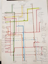
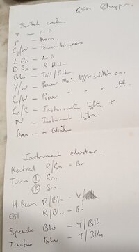
Now you mention it the previous owner builder did send me an early Cycleserv manual as well as a hand drawn colour wiring diagram though it doesn't go into the specifics of the wires out of rotor, strangely..
Here I've photographed it and the colour keys of switches and instruments
Here goes , you will need to zoom...
 

Attachments

  • IMG_20230110_235703.jpg
    IMG_20230110_235703.jpg
    543.6 KB · Views: 44
  • IMG_20230110_235744.jpg
    IMG_20230110_235744.jpg
    102.9 KB · Views: 49
So that indicates a Type B (power regulating) regulator or some kind of screwed-up regulator (as 5twins said) - we didn't make it and can't know what it is and can only go on what you tell us. You also have a homemade wiring scheme and have not supplied a schematic and fail to understand schematics that we (many) supply (in addition to switching stator types from however it was wired).

Have a fire extinguisher and means to disconnect battery handy and......

  1. Connect the black wire from the brush to a good ground that has continuity with battery negative.
  2. Connect the green wire from the the brush to the green wire from the regulator.
  3. Test for magnetism at the rotor with key on

If that produces magnetism, hopefully the rest will work and you can test for charge voltage - 14.2 - 14.5 VDC @ 2500rpm across battery terminals (and no more than that at higher rpm)

Good Luck!
OK @jpdevol I tried your way first as it was easier with the nylon screws still in place, with the connector block still disconnected I located a loose spade terminal and attached it to a spare piece of wire, slipped the spade into the black inner brush slot in the connector to the stator.
I then slotted the green wire spade that was still loose from the last test into the green outer brush slot in the unconnected connector to the stator.
then with one hand I just held the ground wire Id made up from the inner brush held it onto the Negative battery terminal and turned on the key.
Nothing exploded so grabbed a 12mm spanner(wrench) offered it to the rotor nut and it grabbed it strongly!
thats as far as Ive gone.....The sensible thing to do now would be to wait till I hear back from you before proceeding...BUT its 1.10am here, I could wait and see if I hear back from you in say an hour, if not Ill tune in tomorrow to hopefully find out more
Cos looking at how it sits now I have no whites connected, I have the black out of the regulator going to ground on the frame,
and I have the brown from the regulator still connected to switched power,BUT the connector block is still unplugged
HOPE you can understand that, its the best way I can describe it.....Im still lost, its late, Im tired.....
 
Back
Top