Nylon screws

Quick rehash of the type A....

The brown wire is 12v from the ignition switch. It goes to two places:
It goes to the regulator so the regulator knows what the battery voltage is. If it's gonna regulate a charge, it needs to know what the battery's voltage is. The brown wire tells it.
It also goes to the brush. That supplies excitation voltage to the rotor.
So... the brown ties the key, regulator and rotor together. You can run two brown wires from the key to the reg and rotor... or just splice the 3 components together. Makes no nevermind which way you go... as long as you can read 12v at the brush, the reg and the key.... with the key ON.


Black is ground. The black from the regulator goes to the frame... call it earth, call it ground... hell, call it late for dinner. Makes no matter... connect it to the frame. This is the ONLY ground in a type A system. There are NO grounds at the brushes.

Red is the output of the rectifier. This goes straight to the battery (fused of course). This is the charging voltage.

Whites are the 3 AC outputs from the stator. They go to the rectifier.

Green goes from brush to regulator. This is the regulated ground the regulator supplies. We already have 12v at the rotor (brown from key), so when the regulator grounds the green wire, we energize the rotor... causing a charge.


A common troubleshooting method for the type A is to physically ground the green wire at the brush. That will complete the rotor circuit and energize it... generating max charge.

So... try that. Ground the green wire and tell us what happens?
Thank You.
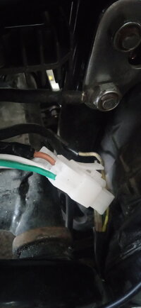
I've got it wired exactly as Jim clearly explains.
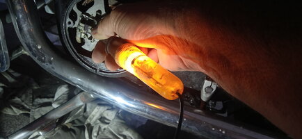
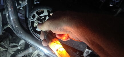
Awake now and in the workshop.
Battery showing 12.7Volts
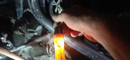
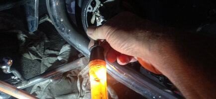
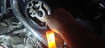
Ground the green brush directly ,no change.
Turn ignition on and ground green brush no change.
Start engine and ground green brush out , no change in volts apart from slight drop of IGN on and eng running.
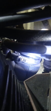
But the thin wire I'm using to ground gets hot where it's touching the frame.
Also note no slapper effect at central rotor nut ign on or off.
Rotor is a rewound unit and ohms at 5.5 then deduct the .5 of the multimeter and its 5.
What else?...oh yesterday double checked the stator ohms and it checked out ok.

Thanks for staying out of it Jan, I know you're trying to help but to me you're not.
Skulls humour is appreciated but wiring diagrams look like Hebrew to me.

Jim's simple concise directions are exactly what I needed.

But the bikes not charging...

Gotta go out for a few hours soon, but I'll be ready to try the next test , fix, or whatever, when I return.
 
Today is another day, I been looking over the last half dozen posts, gonna have another look over it all, there HAS to be something wrong.
Im gonna look at the brown wire as power don't seem to be getting to the rotor
 
@Jim @5twins
Probing at the connector block with key on Im getting battery voltage at the brown wire
BUT...I'm also getting battery voltage at the green wire...
I don't think I should have power at the green...should I?
 

Attachments

  • 16729008486657469466224239367365.jpg
    16729008486657469466224239367365.jpg
    109.5 KB · Views: 37
With key on Im getting power at both brushes and also at the outer rotor ring and was at the inner ring till my testlight probe shorted against the stator housing and blew a fuse
 

Attachments

  • IMG20230105165442.jpg
    IMG20230105165442.jpg
    144.7 KB · Views: 43
  • IMG20230105165443.jpg
    IMG20230105165443.jpg
    151.8 KB · Views: 44
  • IMG20230105165443_01.jpg
    IMG20230105165443_01.jpg
    170.8 KB · Views: 39
  • IMG20230105165456.jpg
    IMG20230105165456.jpg
    161.8 KB · Views: 44
  • IMG20230105165419.jpg
    IMG20230105165419.jpg
    167.5 KB · Views: 40
  • IMG20230105165431.jpg
    IMG20230105165431.jpg
    169.3 KB · Views: 40
Not being Jim or 5twins, but if the black wire to the regulator combo doesn't have a good ground, neither will the green wire. Of course other possibilities exist. (back to butting out)
 
Yeah fellas, nice to see you both back, thought I might have wound up in the
"Too Hard Basket" or the
"Unappreciative Aussie Bastard Basket"

I've got the reg/rec going to a good frame ground, could also ground to battery Neg as well if that might help.
Then again it's chinese so could be suspect.
Didn't think it should be live at both brushes.

To further compound things my '06 Victory Kingpin has a perished intake boot and is now unrideable!
Ordered on from the US last night.
At least I got my Victory Cross Country left in good order and off the the drags for a night of Top Fuel Nitro Action!
All is not lost and you blokes are still talking to me.
Frustrating bloody motorbikes!
I love em!
 

Attachments

  • IMG_20221018_024728.jpg
    IMG_20221018_024728.jpg
    394.3 KB · Views: 41
  • IMG_20221018_103555.jpg
    IMG_20221018_103555.jpg
    208.6 KB · Views: 39
  • IMG20230105203855.jpg
    IMG20230105203855.jpg
    130.9 KB · Views: 42
  • IMG20220914095137.jpg
    IMG20220914095137.jpg
    373.9 KB · Views: 42
Well, this one's got me scratching my head....
Power is present on the black wired brush & Jim asked you (and you complied) to physically ground the green wired brush; that should produce magnetism through the rotor (at a minimum) and (all else good) produce electricity.

I could yammer-on regarding other puzzling events, but "muddying water/ too many cooks" at this point.

:umm:
No mate all the grounding of the green brush produced was a hot finger after holding the wire to ground for a few seconds..
I think from memory the last time I tried something like that I got a pop and smoke and the first reg rec probably got fried.
Something's wrong somewhere..
All else fails this things gonna end up back on ebay.....
 
When you ground the green wired brush, make sure the green wire is disconnected from the regulator (or the brush). You want nothing connected to it but the wire you're using to ground it.
 
OK... for the 'green grounding test' you don't need the bike running.... not sure if you were aware of that or not. Try this....

1. Disconnect the reg/rec.

2. Turn the key on.

3. Touch the green wire screw to ground. You can even use a set of slip joint pliers for this. Spread it out and touch one jaw to the screw and the other to the stator case... which is grounded by it's mounting.

4. Hold a wrench or somesuch close to the rotor nut.

5. The magnetism should pull the wrench to the nut.

Does it?
If it does, how strong is the pull?
OK just got home from a big weekend ,8 hours riding the Victory to get home from the drags (one driver died in a bad crash there tonight)
Jim, you say disconnect the rec/reg...so I unplug the connector block and try 2 ,3,4, and no magnetism!
I wonder at the disconnecting the reg/rec completely and so then remove the green wire from the connector block,
So then plug it back together so only the green is removed from the equation (otherwise how would the rotor get power?)
Then doing 2,3,4 and get good strong magnetism when key is on........pulls the wrench strongly to the nut!

So what does this tell us?.....Also that initial instruction to 1. Disconnect the reg/rec...Did I misunderstand or what?
its 3am here so my guess is its around midday over there but Im dog tired and gonna hit the sack, Ill check the forum again in my morning.
this is getting interesting....
 
Jim, you say disconnect the rec/reg...so I unplug the connector block and try 2 ,3,4, and no magnetism!
I wonder at the disconnecting the reg/rec completely and so then remove the green wire from the connector block,
So then plug it back together so only the green is removed from the equation (otherwise how would the rotor get power?)
Then doing 2,3,4 and get good strong magnetism when key is on........pulls the wrench strongly to the nut!
So what does this tell us?.....Also that initial instruction to 1. Disconnect the reg/rec...Did I misunderstand or what?
We had you disconnect the reg/rec just to remove it from the equation. It's not needed for the slap test. Power to the rotor (brown wire) should be direct from the key. If it didn't work with the reg/rec disconnected... and then did work with it hooked up, you have something mis-wired. Power from the key goes to a splice. That splits it out to the reg/rec and the rotor. With the reg/rec disconnected, you should still have power to the rotor... and grounding the green brush should energize the rotor.

Having to hook up the reg/rec to energize the rotor tells me you have something wired wrong.
@Jim ...ok where then does the wire physically travel to get to the rotor?
On any XS not particularly mine?
 
On the later models, the brown power wire from the inner brush goes up to the big stator plug behind the main frame down tube, behind the carbs .....

StatorPlug.jpg


The harness plug it connects to will have a matching switched power brown wire. But your older harness isn't like that. It won't have that brown wire, you will need to provide it.
 
There's a brown wire coming out of the fuse box from the 10A ignition fuse. It goes down to the reg/rec. Just before, it splits and goes to the rotor brush.


Untitled.png
 
There's a brown wire coming out of the fuse box from the 10A ignition fuse. It goes down to the reg/rec. Just before, it splits and goes to the rotor brush.


View attachment 233397
Thanks fellas BUT not on this one it don't.
This was a custom build from parts it don't follow any particular models rules or layout.
I didn't wire it.
It don't possess a fuse box just a 20 A power fuse.
And I added a 20A fuse to the power feed to battery from regulator when I last did the reg Rec wiring according to Jim's instructions..
Now you'se are saying run another brown wire seperate of the connector to the brush but you don't say which brush..
I need clean clear precise instructions...I know it's difficult when you're not standing alongside the bike with me
I'm a body and paint man with passable mechanical and maintainable skills.
My knowledge of electrics is shocking!
What do I do next?
It's 3pm here so probably around midnight in the US where most of you are.
I'm keen to get the Yammy running and charging and it not wind up back on eBay.
 
The drawing Jim showed is how the 1980 and later U.S. bikes are wired. As I said, yours won't be like that because it's a '79 and older charging system.

The brown switched power wire should feed the inner brush, the one you've isolated with the nylon screws. That's the whole point of using the nylon screws, so you can feed power to that brush without it causing a short.
 
You're overthinkin' this. One brush needs power, the other a regulated ground from the regulator. Which gets which doesn't really matter. Just do as 5twins says and put the power (brown) on the inner brush.

For any electrical component you need two things... power and ground. Power to energize and a ground to complete the circuit.... in this case, ground's controlled by the regulator, the green wire.

Brown don't matter much either. Find a brown that has 12v with the key on and 0v with it off. That's the one you want... run that to the inner brush.
 
Back
Top