pmalace
XS650 Member
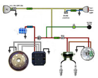
Brand new here and looking to install PMA with PAMCO ignition on my 80 XS650. Looking for as simple wiring diagram as possible to wire in toggle on/off switch with fuses. Keeping it simple with just headlight and brake light. Have seen few diagrams out there but want to be sure correct, running the single coil that came with PAMCO kit. basically want to ensure properly fused and placement of toggle/fuses. any help would be appreciated.

 )
)


 ..a bit of proof reading would be helpful as well..