Yamakazi
XS650 Addict
I have: 1979 XS650SF, stock wiring (except for issue below).
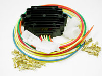
I'm having charging/dead battery issues. In trying to figure it all out, I realized the PO had replaced the individual stock rectifier and regulator with what appears to be a Mike's XS combo rectifier/regulator (Part #24-2089). The replacement combo rec/reg has the same wires and matches with the photo at Mike's website. There are numbers on the back of mine but they tell me nothing (TRM 100384 2/09). I couldn't find any other seller selling a combo unit that looked like this one, so I'm guessing it's Mike's.
I'm just curious about the PO's method of wiring. I'm not sure the PO hooked it up correctly...at least it wasn't installed following the instructions that came from Mike's. My inclination is to re-do the hook-up following Mike's instructions:
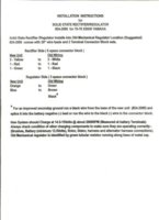
My questions... Why did the PO hook it up this way, and can I re-do this without frying anything? The 2 "dead-ended" black and red wires (that used to connect to the old rectifier) had remnants of previous connections (black had some green, red had some red), as if the rec/reg may've been wired to them at one point. Do you think the PO installed it according to the instructions, but decided it didn't work...and then hooked it up their own way? Or, tried to hook it up right, but did it incorrectly and then found another way?
The current method seems to have the rec/reg red wire bypassing the fuse box, and maybe even the main switch.
Mike's rec/reg vs mine:
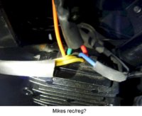
My current rec/reg set-up...
Wiring from the rec/reg:
- 3 yellow correctly wired to the original 3 white (but in a 3-space connector block instead of 6-space)
- orange correctly wired to (harness) green in a second 3-space connector.
- blue is connected to the red/white-stripe wire coming from the starter solenoid switch.
- red goes directly to the (+)battery terminal.
- green goes directly to the (-)battery terminal.
From the harness (original wiring):
- red and black wires (previously bundled with the white wires & connected to the old rectifier) now connect to NOTHING. They were taped and left as dead-ends.
- green (in the green/brown/black 3-space connector) wired correctly to orange
- brown (in the green/brown/black 3-space connector) connects to NOTHING on the opposing side of the connector.
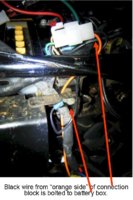
- black (in the green/brown/black 3-space connector) connects to a black wire on the opposing side that runs down to and is bolted to the side of the battery box.
As I understand it, the battery box itself "floats" on rubber dampers and would not provide a proper ground??
I've added pictures to illustrate the current set-up:
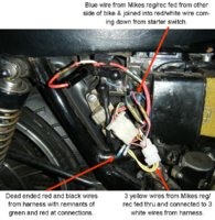
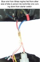
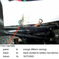
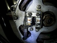
Note: My generator brushes are fed by a black wire and a green wire (no brown down there).

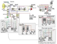
Also...do I need to swap out 3 nylon screws for the 3 steel screws at the brush holder since the 70-79 rec/reg is configured differently than Mikes 80-84 (brown wire) version? I've seen the chart for the 80-84 version with a brown wire:
Whew! Any help would be greatly appreciated.
I'm having charging/dead battery issues. In trying to figure it all out, I realized the PO had replaced the individual stock rectifier and regulator with what appears to be a Mike's XS combo rectifier/regulator (Part #24-2089). The replacement combo rec/reg has the same wires and matches with the photo at Mike's website. There are numbers on the back of mine but they tell me nothing (TRM 100384 2/09). I couldn't find any other seller selling a combo unit that looked like this one, so I'm guessing it's Mike's.
I'm just curious about the PO's method of wiring. I'm not sure the PO hooked it up correctly...at least it wasn't installed following the instructions that came from Mike's. My inclination is to re-do the hook-up following Mike's instructions:

My questions... Why did the PO hook it up this way, and can I re-do this without frying anything? The 2 "dead-ended" black and red wires (that used to connect to the old rectifier) had remnants of previous connections (black had some green, red had some red), as if the rec/reg may've been wired to them at one point. Do you think the PO installed it according to the instructions, but decided it didn't work...and then hooked it up their own way? Or, tried to hook it up right, but did it incorrectly and then found another way?
The current method seems to have the rec/reg red wire bypassing the fuse box, and maybe even the main switch.
Mike's rec/reg vs mine:


My current rec/reg set-up...
Wiring from the rec/reg:
- 3 yellow correctly wired to the original 3 white (but in a 3-space connector block instead of 6-space)
- orange correctly wired to (harness) green in a second 3-space connector.
- blue is connected to the red/white-stripe wire coming from the starter solenoid switch.
- red goes directly to the (+)battery terminal.
- green goes directly to the (-)battery terminal.
From the harness (original wiring):
- red and black wires (previously bundled with the white wires & connected to the old rectifier) now connect to NOTHING. They were taped and left as dead-ends.
- green (in the green/brown/black 3-space connector) wired correctly to orange
- brown (in the green/brown/black 3-space connector) connects to NOTHING on the opposing side of the connector.
- black (in the green/brown/black 3-space connector) connects to a black wire on the opposing side that runs down to and is bolted to the side of the battery box.
As I understand it, the battery box itself "floats" on rubber dampers and would not provide a proper ground??
I've added pictures to illustrate the current set-up:


Note: My generator brushes are fed by a black wire and a green wire (no brown down there).


Also...do I need to swap out 3 nylon screws for the 3 steel screws at the brush holder since the 70-79 rec/reg is configured differently than Mikes 80-84 (brown wire) version? I've seen the chart for the 80-84 version with a brown wire:

Whew! Any help would be greatly appreciated.

