Suddenly, no ignition / startup?

xs750NY

XS650 Member
Messages
22
Reaction score
5
Points
3
Location
New York
Hey all,
So i had my bike out of commission for a few days to do some basic engine work, mostly to do with the carbs and boots and fuel lines, but then i also took the opportunity to do a few simple re routing of wires going to tail lights and signals. Didn't change anything, just relocated the wires and tied them here or there to keep them out of the way.

When i hooked everything back up, i turned the key one click and got no lights whatsoever on gauges. So i turned it back off and disconnected negative and went through all the wires and found some dodgy connections and tightened them. I also noticed that one wire connection was a bit exposed and had been resting against some of the frame. So then i checked all the fuses to see if i had blown one upon startup. All the fuses are good.

So i hook up the battery again and turn the key, but this time i get some lights on the gauges. However, when i go to actually fire up the button, i get no reaction at all. No sound or click or anything. So again i disconnect the battery and check out the throttle wiring. In the past, the ground wire between the engine run switch and frame had a bad connection and needed to be fastened better and then the run button worked. So i thought maybe this was the case again but after trying a few times it didn't do anything.

I get all lights/accessories. horn, signals. But no ignition activity when pressing the button.

So i looked throughly through all wiring on as much of the bike as possible, in particular where i was rerouting some wires. I checked all of them multiple times, and found some weak connections so recreated them.

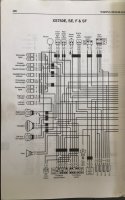
However, i found something that's not attached. I don't know there it is supposed to go though. Please see attached picture. It is a yellow wire with a green stripe, and it's taped up on the end. I looked in the service manual wiring diagram for my bike and didn't find anything yellow-green that this made sense to be other than to do with turn signals. I don't know why it's not connected. I just got this bike a month or so ago, and hadn't noticed this wire. When i saw it today, i saw it tucked down pretty low in there so hadn't noticed it until digging around.

Any ideas what could be causing the ignitition/run to do nothing at all when the button is pressed? Could i have maybe blown something when trying to fire it up? Any ideas what this yellow/green wire might be?
IMG_2017.JPG
 
Last edited:
XS750 triple????............

Guess it depends on your model, In this diagram for a 750E there is a Yellow/green going to the Igniter unit.......There are 2 different units for the 750 models and i'm not sure if the later 750 igniter unit is the same as used on the 850

here is the 750E diagram
750E Assembly  manual27.jpg
 
Thanks guys!
It's a 1979 XS750 Special, which as far as i know is indicated as the XS750 SF.
I looked again in my diagram, but don't see a green/yellow relating to ignition at all.
However, i do see it related to the signal cancelling system. And for what it's worth, my turn signal auto canceling.. never worked. So, that could be that loose wire. For some reason, someone maybe decided to disable the audio canceling?
Anyways, still at square one with the issue.
Any ideas for testing are very welcome!
 
well if all your lights are working ok but not the starter I would take a look at the starter solenoid and its associated wiring.

First make sure that the large red wire that directly connects your battery to the starter solenoid (labeled STARTER SWITCH on the schematic).is connected
The solenoid is constantly live even with the ignition switch off These bikes usually have a large bullet connector in the middle of the red wire so that you can instantly disconnect the battery from the starter if necessary. .

You can do a quick and dirty test on the solenoid if you are careful by bridging the two large terminals on the solenoid with a screwdriver . If that doesn't turn the starter then you have a faulty solenoid or there is no power to the solenoid .

Lastly ...if you have power to the solenoid and the starter is grounded and the starter spins when you bridge the solenoid terminals then you have a fault with the solenoid relay and its wiring or the ignition switch that supplies the relay.
Try wiggling the ignition key at the same time as operating the the starter button and see if you get an intermittant ignition light and or starter motor. Also check the thin red/white wire from ignition switch to the solenoid which powers the solenoid switch

Oh and welcome to the forum XS750NY:thumbsdown:
 
Last edited:
Thank you!!
So, what is the general configuration I should have the bike in when screwdriver-style jumping the solenoid? Am I looking to actually start the bike? Or just leave the engine killed via kill switch on handlebars and have it parked but still try getting the solenoid to have motion for a second then take off the jump connection and it stops? What about the ignition key during this?
Thanks again, and I’m glad to be here ! Not sure if I’ve offended the crowd by talking 750 not 650 but it’s tough to find a good place to get help and this seems like one of them!

I have my multimeter out and ready so might take some readings here and there too.
 
no not starting the bike just testing that the solenoid switch is still working ok. Make sure that you do not touch any part of the chassis or any other metal part with your screwdriver when doing this test.

If you don't feel confident in doing it ......it might be best not to do it in case of accidents. it will spark when you do it so be prepared for that.;)

Make sure the gears are in neutral and the ignition switch is set to off. ;) you're not looking to start the bike with this test although you can do so if your solenoid or the relay is fubar.

hey don't worry about it being a 750 its still an interesting classic bike right ! many of our member have various other classics and modern bikes and they are all of interest.

With your multimeter set to DC volts you could check that there is 12v+ on one of the solenoid terminals with the ignition switched off. No voltage ? then you'll need to find where it is disconnected between the positive battery terminal and the starter solenoid.
 
Ok thank you. Is like to clarify so I understand what I’m actually testing... are the “two large terminals” on solenoid the battery positive and the ground that’s usually getting connected to solenoid circuit via Starter Switch?
Or, is the second “large terminal” the other side of the solenoid voltage pathway that usually is the product of the solenoid operating and delivering the 12V to starter motor?

I’m just wondering what the “screwdriver test” (I may use some heavy gauge wire and gloves instead) is actually jumping, so that I understand what I’m learning from it.

If the two large terminals are case A above, then I’m bypassing/jumping the Starter Switch and witnessing the solenoid work correctly (testing the solenoid). If it is case B above then I’m bypassing/jumping BOTH the Starter Switch and solenoid and basically just testing the starter motor since I’m delivering 12V to the starter motor by way of skipping two obstacles.

Lastly, I don’t see anything in diagrams that indicates “relay” or is a relay schematic symbol, other than the turn signal relay stuff. What does the service manual call it’s stater relay that you’ve referred to maybe being fubar that I can bypass?

NO! not the 2x large terminals and the ground at the same time .........

The starter motor and the starter motor solenoid are both constantly grounded theough the metal bodies where the starter is fixed to the frame (chassis)

All you are doing with the ignition switch off is to short out the 2x large terminals of the solenoid switch with the blade of a screwdriver making sure that the blade of the screwdriver does not touch anything else whatsoever. especially the frame or anything else metal that is attached to the frame.

One of the terminals is constantly live even with the ignition switched off so you should see 12v+ on one of the 2 large solenoid terminals.

The other large terminal connects to the starter motor and there should be no voltage on that terminal until you press the starter button whereupon the starter relay will connect both large red wire terminals together to turn the starter motor. By shorting out the 2 terminals with the screwdriver you are basically bypassing the action of the relay which normally does the job . Its a diagnostic test. If the starter spins then you know the fault has to be with the starter relay

You must be very careful when you do this .

I cannot find a video for a bike so I'll show what is involved testing a car starter and solenoid which is exactly the same in principle .
 
Ok yes I now understand thank you :)
I have refrained from jumping the terminals, and am curious about voltage readings as an alternative to this.
I may have found something symptomatic. But first, let me make sure I have this correct...

When wires are connected properly, one end of the coil that operates the solenoid is provided ground via the handlebar Start button, but otherwise this end of the coil remains not connected to anything electronically.

Then, the opposite end of this coil is... constantly provided 12V, when both the On key is turned and the Engine Stop Switch is in the Run position, correct? (And the battery is fully connected, of course)

As far as I could tell from diagrams, this is the case, is it not?

When I have those factors going above, I am getting a DC reading of 0V on the opposite side of coil from the side that’s provided ground via the start button. . I am expecting to see a constant 12V at that side of the coil. I also am thinking that the method of switching that the coil functions with is that ground is provided to the other end and thus 12V shoots through the coil and engages the solenoid.

Is that the way it’s supposed to work?

If so, then clearly this could be my issue with getting zero activity from the startup. The coil for solenoid does not have its 12V sitting on one end waiting to be pulled through the coil.

Would love to get any thoughts anyone might have! I’m going to also upload the diagram. It’s two pages..
 

Attachments

  • E51CA296-A1F5-4E1E-93DD-74C6B89871CA.jpeg
    E51CA296-A1F5-4E1E-93DD-74C6B89871CA.jpeg
    154.4 KB · Views: 157
  • BB929F6E-89D0-49EF-9CA6-906F94D49DEF.jpeg
    BB929F6E-89D0-49EF-9CA6-906F94D49DEF.jpeg
    140.5 KB · Views: 212
yes I think that you have it. but just to make it as clear as possible I'll recap
There are 2x sides to the starter solenoid switch.

Looking at the coil side

The operating coil side has 2x wires .L/W and R/W

The R/W (red white) wire is the 12v+ power supply to the coil and is fed from the ignition switch via the stop switch and various relays such as the safety relay and possibly the clutch and foot rest etc . This R/W wire becomes live when the ignition switch is turned on

The LW wire is the grounding wire for the coil . As you say it connects to the starter button which grounds the circuit when pressed and energises the solenoid coil.

The starter motor power supply is completely unconnected to the starter motor supply and ground . it is fed with a 12v+ live feed directly from the battery on a heavy red wire connection and is constantly live even with the ignition switch off.Ground is provided vi the metal body and frame fixing.

Ok ...now if with the ignition switch on you should see 12v+ at the R/W terminal on the solenoid coil when you press the starter button. If you do not then there is a break in the connection somewhere.

Check that the STOP switch is central and not switched to STOP its easily done and has stranded me on one occasion ;)
Check to see if there is a side stand switch or clutch switch or other safety relay that is causing a break in the R/W wire 12v+ supply from the ignition switch to the solenoid .

you haven't said what model year your bike is ?

I missed your comment about no 12v+ at the coil. That should be your first task. There should be a heavy red wire connected to the battery which goes directly to the starter motor solenoid . It does not go through a fuse or relay or anything else. Trace the wire from the battery to starter. Put you positive mulltimeter probe on the red wire at the starter and the black negative probe on the negative terminal of the battery
 
Last edited:
Perfect, yes fully understood! Thank you!
I’m in the habit of always using the engine cutoff switch so am definitely having it in Run for these tests.

So I took a few readings, working from the battery and downstream via all the fuses.
I get through the first two fuses with full voltage, but then the fuse immediately prior to the engine cutoff switch gives me readings I don’t understand so I’m now suspicious of the fuse there.

With the engine cutoff turned off, I get only around 2.8 to 3V after the fuse. Then with the engine cutoff switch engaged to Run, the reading (which is taken after the fuse but before the switch) drops to 0. So, something is up in this area.

I pulled the fuse and am heading out to pick up a new one. Something concerning is that the fuse in service manual is supposed to be 10A, but the actual fuse says 25A on it. Hopefully it hasn’t passed a super strong current and blown something down the line (like the solenoid). Also the fuse is rather corroded inside. I had done a continuity test on all fuses and they all passed, but I guess I don’t know enough fuse properties. Maybe not enough voltage can pass through it to engage the solenoid, and only around 3V is getting through.

Anyways I’ll see what happens when I pop in a new one (and it will be proper 10A).

I might also clean the fuse case itself with DeOxit.

I’m also concerned that the downstream side of the engine cutoff switch is getting grounded somehow. I have just opened up and inspected and cleaned all of my handlebar switches and buttons, so I don’t think that should be the issue.
 
Ok, it seems my issues are possibly a bit more complicated than i'd hoped, unless i'm not actually supposed to get a full 12V approx on the lines spawned off from the engine run switch.
I get about 7-8V when taking readings after the fuse with the engine cutoff switch turned on.
I know that when one has multiple destinations for a signal and it's not buffered, each destination is drawing it's own share of the signal and the signal voltage will go down some with each destination that you add.
However, i disconnected the solenoid, and also disconnected the 6 pin connector that goes the Ingintion Unit, so all that is left is the three ignition coils that are part of the spark plug system.
The reading is still about 7-8 Volts. Unchanged from the reading taken with all connected still.

Does this sound like i have a busted ignition coil or something? Or a partial fault somehow in that area? Seems like some signal is sunk, but around half remains.

Any thoughts?
 
what is the year of your bike ? remember this is a xs650 forum and we don't have schematics for the xs750 as far as I know.

here is a picture of a typical XS750 starter solenoid.
One of the larger terminals should be connected directly to the starter motor (red wire)
This terminal should have no voltage on it until the starter button is pressed

The other large terminal (also red wire ) should connect directly to the positive terminal on your battery. ....Do you have 12v+ on this terminal ?
xs750 solenoid.jpg
 
Last edited:
thank you. yes i have the connections in mind correctly.
if you scroll up a few posts ago, there are two attachments. That is the wiring diagram of my bike. To see in full resolution, you need to just click on them to open them and maybe right click and/or "save as" or "open image in new tab". That kind of thing.
The bike is a 1979 XS750 SF
I could always just try starting up the bike with these voltages. There is around 7.5V on the point that feeds the solenoid, one point of the ignition unit, and the ignition coils for spark plugs. Maybe it's supposed to be 7.5V?
 
Maybe it's supposed to be 7.5V?
No. Voltage across the system should be about the same as battery voltage... with a slight line loss. On the 650 a half a volt loss is considered excessive. I'd call that the upper limit for your bike also. You've got some high resistance somewhere. Either a connector or possibly the iggy switch or kill switch. Did you have the headlight bucket open?
 
Last edited:
Yes I have it open. What’s to look for in there, given this symptom?
What I meant was.... did you have it open... were you rearranging in there before the problem started. The kill sw.... iggy sw. all kinds of stuff connects in there. If I were moving stuff around in there... and afterwards had a problem, I'd look in there for something loose or wired wrong.
 
Nope. I had been repositioning the rear wiring, such as the tail light and rear blinkers. Also pushed around some fuse/wires under seat to a better spot. I took pictures to make sure things were returned to as is. I found a couple weak connections in wiring there and recreated them.
After that is when the bike don’t even get panel indictor lights upon turning key. Then I went and found that one wire going to a rear blinker had been resting against chassis by pure luck at a small exposed spot on the wire. So I taped that up, double checked all connections, and we’re at where we’re at which is 1/2 DC voltage at point that feeds multiple aspects of the bike
 
Also pushed around some fuse/wires under seat to a better spot.
There's as good a place as any to start.
Just so's we're on the same page here... With the key on, you're still getting a solid 12V at the battery, but about half that on anything downstream.... correct?
 
Back
Top